2 61287723G1-22B
.
3. Trim the insulation back 1/2” on the ground wire and attach a #10
ground lug.
4. Route the ground wire as shown in the figure below and attach it to
the ground terminal post just below the Electronics Module.
5. Replace the rubber grommet in the housing (Step 3).
6. Route the ground wire 12 inches below finished grade by the
shortest and most direct route to the AC power ground system
Multi Grounded Neutral (MGN) of the customer premises. Ensure
the wire is free of any sharp bends.
7. Attach the ground wire to the subscriber premises with stainless
steel half moon clamps or tie-wrap the ground wire to the riser
conduit of the Buried Fiber Drop.
8. Clean the MGN connector with emery cloth to insure a stable
connection.
9. Attach the ground wire from the 372E SBU ONT to the MGN
connector with the appropriate UL approved ground clamp/fitting.
10. Coat the connection with a metal corrosion preventative.
11. Attach a Warning Ground Tag to this grounding connection.
Step 4: Connect Power and Alarm Cables
Wiring the Power/Alarm connector improperly could damage the SBU.
The 372E SBU ONT is supplied with a 7-conductor Euro-style Power/
Alarm connector. To make connections from the UPS to the power
connector, refer to the figure and Power/Alarm Pin Out Table below and
complete the following steps:
1. If necessary, remove the Power/Alarm connector by pulling it out
of the electronics module.
2. Remove the rubber grommet from the housing and insert the
Power/Alarm cable through the grommet.
1
2
3
Use this example for all grommet and ber/cable installations.
Ground
Note: The wire color used in this
and all other illustrations is for
clarity purposes only.
Pin 1
Pin 7
1
2
3
4
5
6
7
UPS Power Connector
Power/Alarm
Connector
+12VDC
12V Return
Signal Return
On Battery
Replace Battery
Battery Missing
Low Battery
Assorted tie wraps for securing cabling and wiring
Installation Steps
To install the 372E SBU ONT, complete the following steps:
Step 1: Mount the Enclosure
Complete the following steps to mount the enclosure:
1. Choose a vertical surface near an approved ground and away from
any water source. The subscriber should have easy access for test-
ing.
2. Use the top and side external mounting holes as a template to mark
fastener locations. Use a level to ensure the unit is level to prevent
warping. For an indoor mount, prepare the mounting surface by
attaching a 3/4 inch plywood board to the wall studs. This provides
long-term stability for the 372E SBU ONT.
3. Pre-drill the marked locations and install fasteners or anchors
appropriate to the mounting surface (each anchor rated to 18 lbs or
8.2 kg minimum).
4. Mount the 372E SBU ONT.
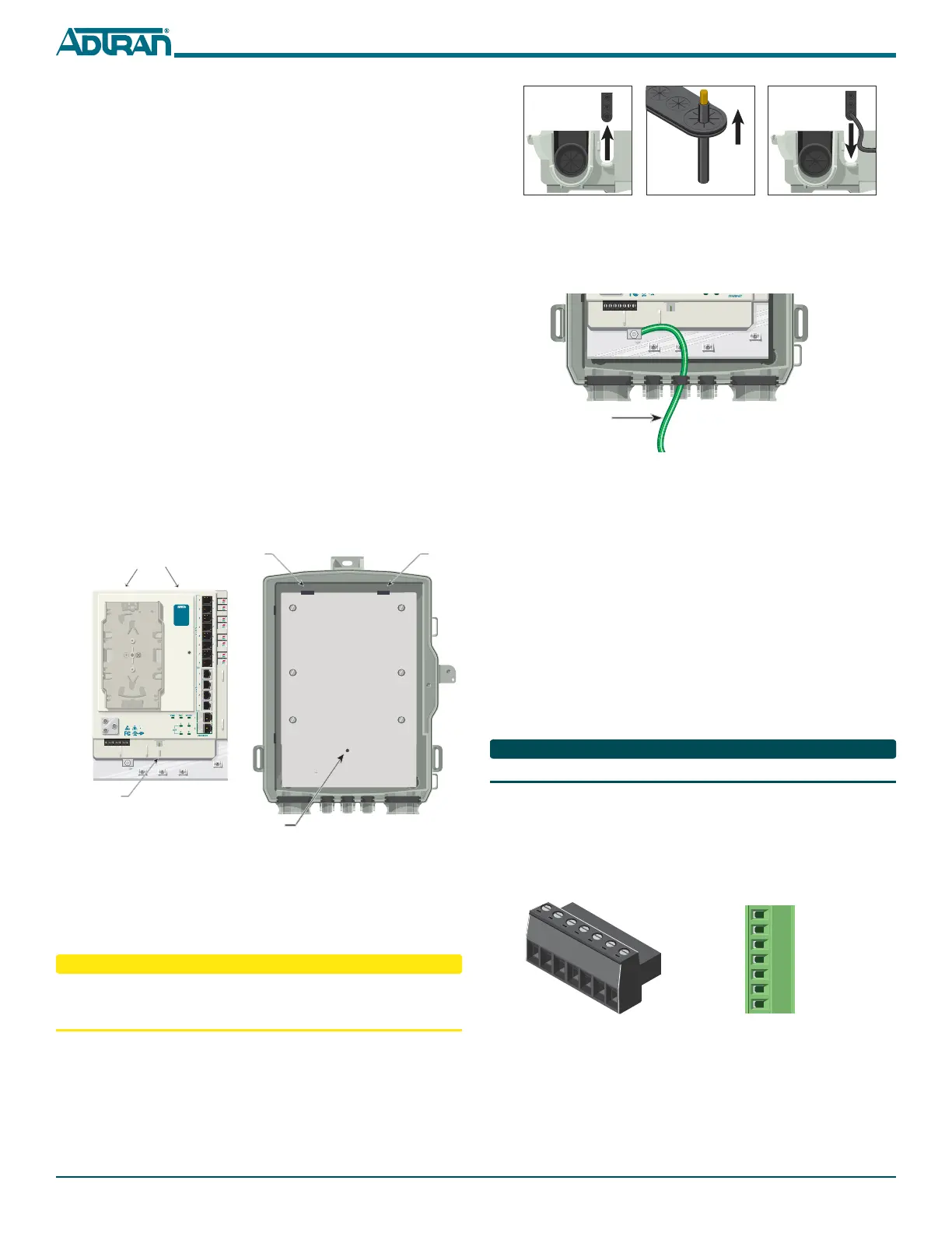
Step 2: Install the Electronics Module
The Electronics Module has a protective cover that prevents access to the
POTS, Ethernet and DS1 connections. To access these connections, loosen
the Telco Access screw on the protective cover.
Refer to the following illustration and procedure when installing the
Electronics Module in the Enclosure:
1. Align the slots on the reverse of the Electronics Module with the
tabs on the Enclosure.
2. Slide the Electronics Module on to the tabs and align the Screw Slot
with the Threaded Hole.
3. Secure the Electronics Module using the #6 (PN 3276003003-E)
screw provided.
Do not use a knife to cut openings in the rubber grommets. This may
result in an excessively large holes and compromise the integrity of the
unit allowing moisture into the unit.
Step 3: Install Ground Cable
Refer to the figures below and install the ground connection by
completing the following steps:
1. Remove the rubber grommet from the housing (Step 1).
2.
Route a #6 ground wire through the rubber grommet (Step 2).
Screw Slot
Threaded Hole
Slots on Reverse
Tab Tab
TELEPHONE TROUBLESHOOTING:
1. Identify the bad line (POTS 1-8).
2. Plug any working phone into
the appropriate jack.
If the telephone works, the unit
is functioning normally.
If the telephone does not work,
contact your service provider.
3. Remove the telephone from the
POTS jack.
TOTAL ACCESS 372
1287722G1
Backplate
 Loading...