61287723G1-22B 3
3. To terminate the two UPS power leads (Pins 6 and 7) and, if needed,
the five alarm status leads in the Power/alarm connector, cut all
wires and strip back the insulation. Use a flat head screwdriver (or
similar device) and loosen all the screws on the Power/Alarm
Connector. Insert one wire at a time and tighten the screws to make
an electrical contact.
4. Reconnect the Power/Alarm connector to the bottom of the
Electronics Module.
5. Tie Wrap the wires to the tie-wrap anchors just below the
Electronics Module.
6. Replace the rubber grommet.
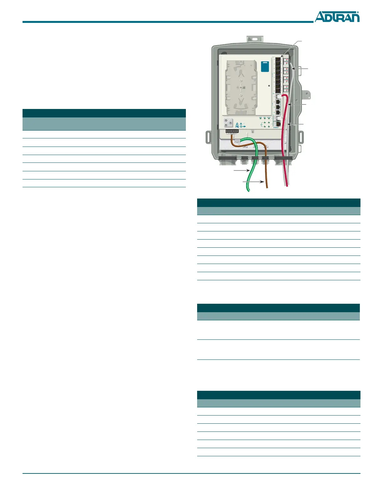
Step 5: Connect POTS
The telephone service or POTS connection is provided through pivot-
connectors located on the right side of the Electronics Module. These also
provide a diagnostic test point. Inserting an RJ-11 jack (i.e., telephone
cable or telephone test set) will connect the telephone set to the 372E SBU
ONT and also disconnect the subscriber service from the 372E SBU ONT
providing fault isolation to the SBU or premises wiring.
To terminate the POTS connections, refer to the figure in the next column,
and complete the following:
1. Remove the rubber grommet from the housing and insert the POTS
cables through the grommet.
2. Trim each wire to length. Identify each pair in the service cable.
3. Flip the pivot connector to the “up” position.
4. Insert the appropriate wires
TIP (green) and RING (red).
5. Flip the pivot connectors to the “down” position.
6. Replace the rubber grommet in the housing.
Step 6: Install Ethernet and DS1 Connections
The SBU ONT supports 2 Gigabit operations. The cable used should be
rated CAT-5 or 6. To install the Ethernet and DS1 connectors, refer to the
figure below and complete the following steps:
1. Route the cables for the Ethernet and DS1 through the same open-
ing as the POTS cables.
2. Trim back the jacket of the subscriber Ethernet cable and connect the
4-pair twisted wires to the RJ-45 Plug using an RJ-45 crimper. The
Ethernet Pin Out table below lists the individual pin out
designations.
3. Insert the terminated RJ-45 jack into the appropriate
ETHERNET
1–2
socket on the 372E SBU ONT.
Power and Alarm Connector Pin-outs
Pin-Out Power and
Alarm Connector
Description Pin-Out UPS
Connector
1LOW BAT1
2BAT MIS2
3 REP BAT 3
4ON BAT4
5SIG RTN5
612V RTN6
7+12VDC 7
Refer to the Ethernet LED Connectivity table below to determine Ethernet
status.
4. For the DS1 connection trim back the insulation on the subscriber
DS1 cable and connect the wires to the RJ-45 connector using an RJ-
45 crimper. Connect the DS1 cables per the table below.
5. Tie wrap all cables to the appropriate Tie wrap anchor points.
Ethernet RJ-45 Pin-out
Pin Name Description Color Code
1 TRD0+ Transmit/Receive Positive White/Orange
2 TRD0- Transmit/Receive Negative Orange
3 TRD1+ Transmit/Receive Positive White/Green
4 TRD2+ Transmit/Receive Positive Blue
5 TRD2- Transmit/Receive Negative White/Blue
6 TRD1- Transmit/Receive Negative Green
7 TRD3+ Transmit/Receive Positive White/Brown
8 TRD3- Transmit/Receive Negative Brown
Ethernet LED Connectivity
Label Status Description
LINK
Off
Green
Link is down or Administratively
shut down
10/100/1000 link is up
ACTIVITY
Off
Yellow Flashing
No activity, or Administratively
Shut Down
TX or Rx activity
DS1 RJ-45 Pin-out
Pin Name Description
1 Rx Data (Ring) From customer to Network Interface
2 Rx Data (Tip) From customer to Network Interface
3Not Used
4 Tx Data (Ring) From Network Interface to customer
5 Tx Data (Tip) From Network Interface to customer
6–8 Not Used
Ethernet
Connection (White)
DS1
Connection (Red)
Tip (Green)
Ring (Red)
Note: The RJ-11 POTS
ports are used for test
purposes only.
TELEPHONE TROUBLESHOOTING:
1. Identify the bad line (POTS 1-8).
2. Plug any working phone into
the appropriate jack.
If the telephone works, the unit
is functioning normally.
If the telephone does not work,
contact your service provider.
3. Remove the telephone from the
POTS jack.
TOTAL ACCESS 372
1287722G1
Power
Ground