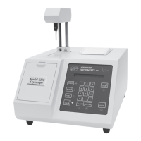
Power module (Figure 7)
The power module on the rear of the instrument contains the following
components.
• Power switch
The rocker-style power switch controls the power to the instrument.
The power switch may be left on continuously; the 4250 enters
standby mode automatically if idle for more than 5 minutes.
• Power cord connector
The power cord connector accommodates a power cord suitable for
the power available.
• Fuse holder
The fuse holder contains the instrument’s necessary fuses. For
instructions on replacing fuses, see Chapter 5.
RS-232 port (Figure 7)
The RS-232 port allows you to output your instrument’s data/messages
to an external device, such as a computer. For more detailed information
dealing with the RS-232 port, please read the section titled “Using the
4250’s RS-232 port”, which is found later in this chapter.
Barcode port (Figure 7)
A D-type, 15-pin barcode port is provided in the back of the 4250 for
connecting and providing power to such a device. For proper operation,
the barcode port requires a 1200 bps, RS232-level signal providing
asynchronous serial data containing 1 start bit, 8 data bits, 1 stop bit and
no parity.
Advanced
®
Cryoscope Model 4250 User’s Guide
16
+5V DC 1 to reader
receive data 10 from reader
gnd/earth 9 common
Signal Pin Direction
Table 2: Barcode Port Connections
 Loading...