Home
Advantech
Gateway
ADAM-4572
Page 37 (Figure 2.37 Wiring RS-485 Connection)
Advantech ADAM-4572 - Figure 2.37 Wiring RS-485 Connection; Figure 2.38 Wiring RS-422 Connection
62 pages
Manual
Save Page as PDF
To Next Page
To Next Page
To Previous Page
To Previous Page
Loading...
31
ADAM-4572 & EKI-122X
Series User Manual
Chapter 2
Getting
Started
Wiring for RS-485 Connec
tion
Figure 2.37 Wiring RS-485 Co
nnection
Wiring for RS-422 Connec
tion
Figure 2.38 Wiring RS-422 Co
nnection
36
38
Table of Contents
Main Page
Default Chapter
3
Declaration of Conformity
3
Safety Instructions
4
Table of Contents
5
Chapter 1 Introduction
7
Overview
8
Features
8
Package Check List
9
Chapter 2 Getting Started
11
Understanding Modbus Gateways
12
Protocol Overview
12
Figure 2.1 Modbus System Architecture 1
13
Figure 2.2 Modbus System Architecture 2
13
Modbus RTU
14
Modbus ASCII
14
Table 2.1: Comparison of Modbus RTU and ASCII Modes
14
Modbus TCP
14
Specifications
15
Eki-1221/1222/1224
15
Eki-1221D/1222D
16
Adam-4572
17
Hardware
18
LED Indicators
18
Table 2.2: EKI-1221/1222/1224, EKI-1221D/1222D LED Indica Tors
18
Table 2.3: ADAM-4572 LED Indicators
18
Dimensions (Units: MM)
19
Figure 2.3 Front View of EKI-1221
19
Figure 2.4 Side View of EKI-1221
19
Figure 2.5 Back View of EKI-1221
20
Figure 2.6 Top View of EKI-1221
20
Figure 2.7 Front View of EKI-1222
21
Figure 2.8 Side View of EKI-1222
21
Figure 2.9 Back View of EKI-1222
22
Figure 2.10Top View of EKI-1222
22
Figure 2.11Front View of EKI-1224
23
Figure 2.12Side View of EKI-1224
23
Figure 2.13Back View of EKI-1224
24
Figure 2.14Top View of EKI-1224
24
Figure 2.15Front View of EKI-1221D
25
Figure 2.16Side View of EKI-1221D
25
Figure 2.17Back View of EKI-1221D
26
Figure 2.18Top View of EKI-1221D
26
Figure 2.19Front View of EKI-1222D
27
Figure 2.20Side View of EKI-1222D
27
Figure 2.21Back View of EKI-1222D
28
Figure 2.22Top View of EKI-1222D
28
Figure 2.23Front View of ADAM-4572
29
Figure 2.24Back View of ADAM-4572
29
Figure 2.25Bottom View of ADAM-4572
30
Figure 2.26Side View of ADAM-4572
30
Connecting Hardware
31
Choosing the Location
31
Figure 2.27Combine the Metal Mounting Kit
31
Figure 2.28ADAM-4572 Panel Mounting Bracket Dimensions
32
Figure 2.29ADAM-4572 Panel Mounting
32
Figure 2.30DIN-Rail Step 1
33
Figure 2.31DIN-Rail Step 2
33
Figure 2.32DIN-Rail Adapter
34
Figure 2.33DIN-Rail Mounting
34
Connecting Power
35
Figure 2.34Power Connector
35
Connecting Serial Devices
35
Figure 2.35EKI-122X Series Serial Port Pin Assignments
35
Connecting to a Host or the Network
36
ADAM-4572 Serial Port Wiring
36
Figure 2.36Wiring RS-232 Connection
36
Figure 2.37Wiring RS-485 Connection
37
Figure 2.38Wiring RS-422 Connection
37
Configuration
39
Chapter 3 Configuration
39
Installing the Configuration Utility
40
Starting the Configuration Utility
43
Discovering Modbus Gateways
44
Auto Searching
44
Clear Device List and Search Again
47
Manual Appending
47
Setting Ethernet Parameters
48
Setting Serial Communication Parameters
49
Basic Configuration
50
Operation Configuration
52
Function Accessible Setting
55
Monitoring Modbus Status
56
Administrator Setting
56
Import/Export Serial Port Setting
57
Locate the Modbus Data Gateway
57
Lock Device
58
Restore to Factory Default Settings
59
Update Firmware
60
Related product manuals
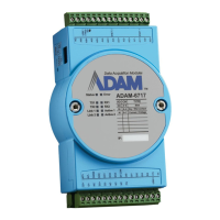
Advantech ADAM-6717
44 pages
Advantech ADAM-6700 Series
44 pages
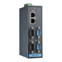
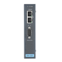
Advantech EKI-1221
48 pages
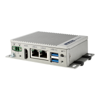
Advantech UNO-2271G V2
60 pages
Advantech WISE-710
3 pages
Advantech ECU-1251 Series
28 pages