Do you have a question about the Advantech UNO-2271G V2 and is the answer not in the manual?
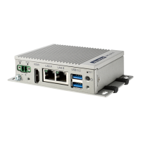
Overview of the UNO-2271G V2 series and its features.
Essential safety guidelines for handling and connecting the device.
Details the items included in the product package.
Technical specifications including dimensions, weight, and system components.
Provides detailed physical dimensions of the UNO-2271G V2, with and without kits.
Explains motherboard and extension kit connectors and their locations.
Details the external connectors on the front and rear panels of the base unit.
Describes internal connectors on optional expansion kits for added functionality.
Instructions for properly grounding the device for EMI protection.
Guide for connecting the approved power adapter or DC power source.
Steps to remove and reattach the bottom cover for internal access.
Procedures for attaching optional 2nd stack extension kits to the device.
Details the pin assignments for the DC power input connector.
Provides pin assignments and LED status for the Gigabit Ethernet port.
Lists pin assignments for the USB 3.0 connector.
Details pin assignments for the HDMI output connector.
Lists pin assignments for the M.2 B-key connector.
Provides pin assignments for the M.2 E-key connector.
Details pin assignments for the mPCle connector.
Explains COM port modes and configuration via switches.
Describes jumper settings for AT/ATX power mode selection.
Lists pin assignments for expansion board connectivity.
Instructions for enabling/disabling TPM 2.0 functionality in the BIOS.
Guide for enabling/disabling CPU Turbo mode via BIOS settings.
Instructions for enabling/disabling TCO for Watchdog OS support in BIOS.