9 UNO-2271G_V2 User Manual
Chapter 2 Hardware Functionality
2.1.2 Base Unit's External I/O Connector
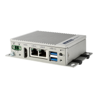
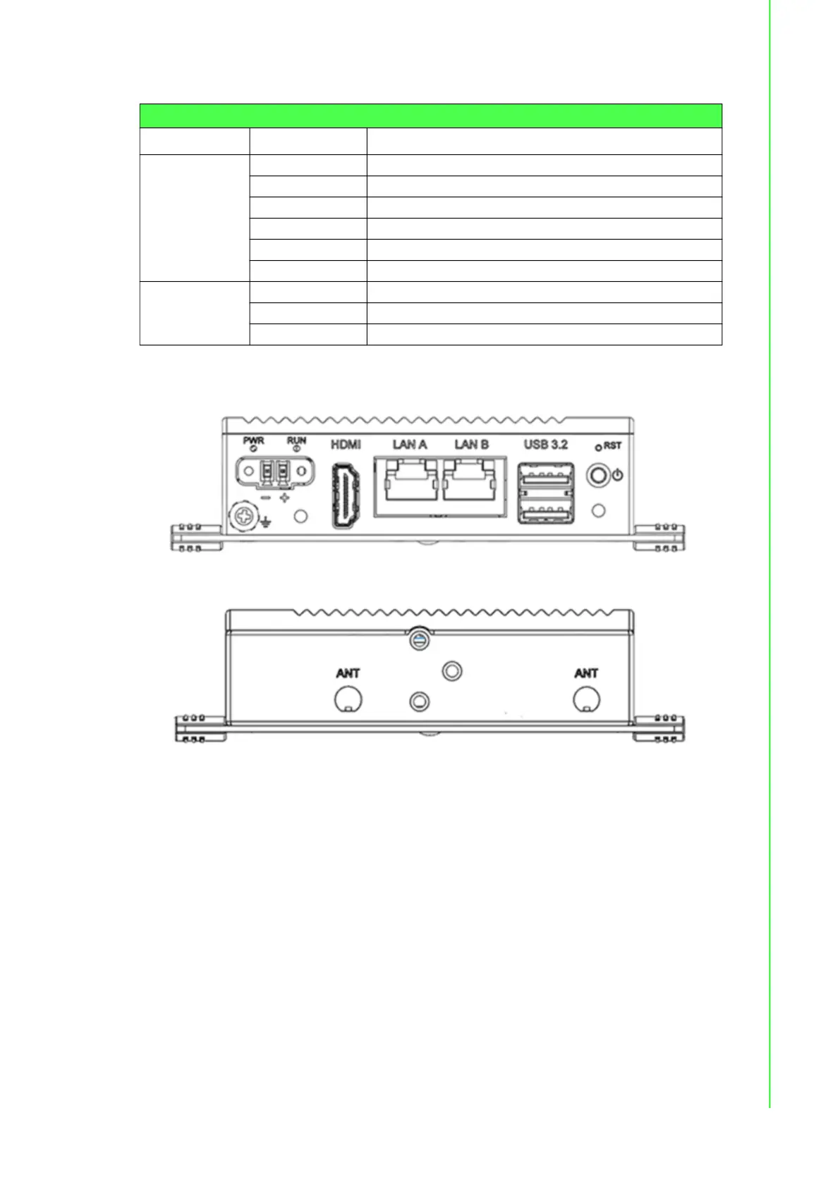
Figure 2.3 Front Panel of UNO-2271G V2
Figure 2.4 Rear panel of UNO-2271G V2
2.1.2.1 Power Connector
UNO-2271G V2 comes with a Phoenix connector that carries 10 - 30 V
DC
external
power input, and features reversed wiring protection. Therefore, the system will not
accrue damage from reversed polarity of ground lines and power lines. (Please refer
to User Manual - Appendix A.1 for pin assignments)
2.1.2.2 LAN: Ethernet Connector
UNO-2271G V2 is equipped with two Gigabit LAN controllers. An Intel
®
i211 or i210
Ethernet controller that complies with IEEE 802.3u 10/100/1000 Base-T is used as
the controller chip. The Ethernet port is a standard RJ-45 jack. Additionally, LED indi-
cators are provided on the front of the device to indicate the system’s Link (off/green/
orange) and Active (green) status. (Please refer to User Manual- Appendix A.2 for
pin assignments.)
Table 2.1: Key Components, Connectors on Motherboard
Category Label Function
External
PW1 Power button
RST1 Reset button
CN1 HDMI connector
LAN1 LAN connector
USB1 USB 2.0+3.0 connector
DCIN1 DC input connector
Internal
CN2 Expansion B2B connector
CN3 MiniPCIe connector
BAT1 RTC battery connector
 Loading...