UNO-2271G_V2 User Manual 34
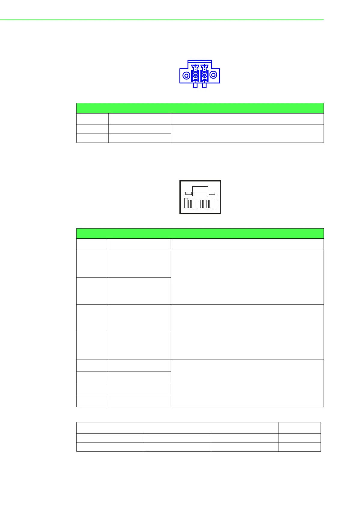
A.1 Power Connector (DCIN1)
A.2 LAN: Ethernet Connector (LAN1)
Table A.1: Power Connector Pin Assignments
Pin Signal Description
1 Power IN V+
10 - 30 V
DC
2 Power IN V- (GND)
Table A.2: Ethernet Connector Pin Assignments
RJ45 Pin Signal Description
1 MDI0+
In BASE-T: Media Dependent Interface[0]:
1000BASE-T: In MDI configuration, MDI[0]+/- cor-
responds to BI_DA+/- and in MDI-X configuration
MDI[0]+/- corresponds to BI_DB+/-.
10BASE-T and 100BASE-TX: In MDI configuration,
MDI[0]+/- is used for the transmit pair and in MDIX
configuration MDI[0]+/- is used for the receive pair.
2 MDI0-
3 MDI1+
In BASE-T: Media Dependent Interface[1]:
1000BASE-T: In MDI configuration, MDI[1]+/- cor-
responds to BI_DB+/- and in MDI-X configuration
MDI[1]+/- corresponds to BI_DA+/-.
10BASE-T and 100BASE-TX: In MDI configuration
MDI[1]+/- is used for the receive pair and in MDI-X
configuration MDI[1]+/- is used for the transmit pair.
6 MDI1-
4 MDI2+
In BASE-T: Media Dependent Interface[3:2]:
1000BASE-T: In MDI and in MDI-X configuration,
MDI[2]+/- corresponds to BI_DC+/- and MDI[3]+/ -
corresponds to BI_DD+/-.
100BASE-TX: Unused.
10BASE-T: Unused.
5 MDI2-
7 MDI3+
8 MDI3-
Left LED Right LED
10 Link 100 Link 1000 Link Active
Off Orange Green Green