UNO-2271G_V2 User Manual 8
2.1 Introduction
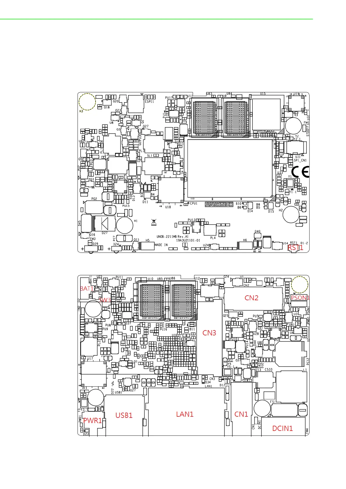
The following diagram demonstrates the location of UNO-2271G V2’s motherboard
and extension kit’s internal/external connectors.
2.1.1 Base Unit's Internal Connectors
Figure 2.1 Diagram of Connector Locations on UNO-2271G V2 (Top Side)
Figure 2.2 Diagram of Key Components Location on UNO-2271G V2
(Bottom Side)