vii UNO-2271G User Manual
Contents
Chapter 1 Overview...............................................1
1.1 Introduction ............................................................................................... 2
1.2 Safety Precautions .................................................................................... 2
1.3 Accessories............................................................................................... 3
Chapter 2 Hardware Functionality.......................5
2.1 Introduction ............................................................................................... 6
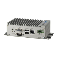
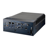
Figure 2.1 Front Panel of UNO-2271G-E21AE for one stack model
which can support extra extension kit UNO-2271G-
EKAE.......................................................................... 6
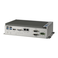
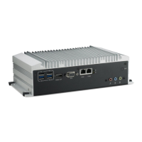
Figure 2.2 Front Panel of UNO-2271G-E22AE for two stack model
which can support extra 3 x USB and iDoor module.. 6
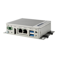
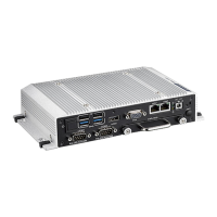
Figure 2.3 Front Panel of UNO-2271G-E23AE for two stack model
which can support extra 2 x COM port and iDoor mod-
ule............................................................................... 6
2.2 UNO-2271G Interface ............................................................................... 7
2.2.1 COM Port Interface (COM 1, COM 2)........................................... 7
2.3 LAN: Ethernet Connector.......................................................................... 7
2.4 Power Connector ...................................................................................... 7
2.5 USB Connector ......................................................................................... 7
2.6 RTC Battery Specification......................................................................... 8
2.7 Power Button/Power Management ........................................................... 8
2.8 Reset Button ............................................................................................. 8
2.9 PCI Express Mini Card Socket.................................................................. 8
Chapter 3 Initial Setup ..........................................9
3.1 Chassis Grounding.................................................................................. 10
Figure 3.1 Chassis Grounding Connection................................ 10
3.2 Connecting Power................................................................................... 10
Appendix A System Settings and Pin
Assignments......................................11
A.1 System I/O Address and Interrupt Assignment ....................................... 12
Table A.1: Interrupt Assignments............................................... 12
A.2 Board Connectors and Jumpers ............................................................. 12
Figure A.1 Connector & Jumper Locations for UNO-2271G-
N2AE(front)............................................................... 12
Table A.2: Connectors and Jumpers ......................................... 12
A.3 Power Connector (PWR)......................................................................... 13
Table A.3: Power connector pin assignments............................ 13
A.4 USB Connector ....................................................................................... 13
Table A.4: USB 2.0 Connector Pin Assignments....................... 13
Table A.5: USB 3.0 Connector Pin Assignments....................... 13
A.5 HDMI Display Connector......................................................................... 14
Table A.6: HDMI Display Connector.......................................... 14
A.6 COM1/COM2 RS232/422/485 connector................................................ 14
A.7 Mini PCIE slot (MINIPCIE) ...................................................................... 15
A.8 LAN RJ45 connector ............................................................................... 16
A.9 Screw Type and Quantity for Mounting Module ...................................... 17