ᆅჾ
ۉጱྃഗ
֪
য়ߢ༵๖ణ
INTRO
TRIP UNIT
LOCKS ACCESSORIES TESTS APPENDIX
1.4-05
ᆅჾࡀ߭Ҿጎ֡ፕۉጱྃഗ
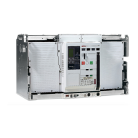
ୟഗ
BREAKER
NF1:ဣଚگუഘୟഗ
ޏሶۉጲۯྺڑࣟዘႎئీă
..!ൽူᄩ߇ࠓ௬ӱฉڦᆶࠬă
..!ඓԍࡋ0௬ӱோᅙ࠲Կă
֡ፕǖ
2/!ٗ٪ݣ࿋ዃൽᄩդDŽ!2/:Džă
3!/!ٗդా؏౦߇Lj!ჽդDŽ!2/21Džă
4/!֭ᅃጴ๕அີژժገۯ!:1ŃLjٶᄩ߇ࠓڔӱă
DŽ֖!2/22Dž
5/!֭ᄩդLjొ้ኍገۯă࿋ዃኸ๖ഗٗ
DPOOFDUFEDŽথDžᅎۯڟ!UFTUDŽ֪DžDŽ!
2/22CDžLjፌዕᅎۯڟ!EJTDPOOFDUFEDŽDž࿋ዃă
ጀᅪǖ!ᄩդ࿋ᇀᄩ߇ࠓዡా้Lj
ୟഗփీሞ!D!P!O!O!F!D!U!F!E!DŽ!থDž!ࢅ
EJTDPOOFDUFEDŽDžኮڦඪࢆ࿋ዃฉۯፕă
ൽူդLjᄩդڔӱࣷጲۯް࿋ă
6/! ٗ! EJTDPOOFDUFEDŽDž࿋ዃ๔Ⴤొ้ኍገ
ۯᄩդLjڟٳമڔӱă
ጀᅪǖٗ! EJTDPOOFDUFEDŽDž࿋ዃൽኮമLjඓԍ
ԿࢇڑࣟڦئీᅙྜඇݣDŽڑࣟئీኸ๖ഗ၂๖ྺĐ࿄
ئీđDžă
7/!ୟഗُ้࿋ᇀྼႪ࿋ዃDŽ!2/23Džă
ᅜሞ࿋ዃฉٶࡋ0௬ӱோLj༵ื߾থڟ༵ื
ࠬࠍฉLjࠬࠍᅜٗୟഗፑᆸଇ֨ۥևઙDŽ֖!
2/32Džă
2/5/7!֭ୟഗ
ጚԢǖ
..!ٗ؏๕ኧࣂࡆฉൽူࠬă
..!ൽူ؏ฉڦᆶഄࠬă
..!ᆶ؏ă
2/! ၭ႐ୟഗݣዃڟྜඇฦڦ؏๕ኧࣂࡆฉLj๑
ࡐዡኟඓౚࢇăDŽ!2/23Dž
3/!ൽူยԢฉথڦ༵ื߾ă
4/! ܔ௬ӱแუ૰DŽፑᆸଇ֨ۥև൶ᇘDžLjୟഗླྀ
؏Ljփీᅎۯă
5/!࠲Կࠓ0௬ӱோă
6/! ӀቷฉຎຫጚԢ؏ࢅᄩդDŽօየ! 2ڟ! 5DžLj
դ֭ాă
7/! ຩ้ኍገۯᄩդLjୟഗᅎۯڟ؏ాăᅜٗ
࿋ዃᅎۯڟ֪࿋ዃLjࢫᅎۯڟথ࿋ዃLjස࿋ዃኸ
๖ഗ๖DŽ2/22CDžă
Otherwise the motor will recharge the springs --
Remove any padlocks from the racking panel.
-- Ensure the cabinet/panel door is closed.
OperaƟon:
1. Remove the racking handle from its storage locaƟon (Fig. 1.9).
2. Pull out the torque bar from inside the handle and extend
the grip arm (Fig. 1.10).
3. Open the racking aperture shuƩer by inserƟng and rotaƟng
a Ňat screwdriver by 90°. (see Fig.1.11)
4 . Insert the racking handle and rotate counterclockwise.
The posiƟon indicator moves from the CONNECTED through
the TEST (Fig. 1.11B) to DISCONNECTED posiƟons.
NOTICE: When the racking handle is inserted in the racking
shaŌ, the circuit breaker cannot be operated in any posiƟon
between
CONNECTED and DISCONNECTED.
Removing the handle automaƟcally resets the racking handle
shuƩer.
5. From the DISCONNECTED posiƟon, conƟnue turning the
racking handle anƟ-clockwise unƟl reaching a posiƟve stop.
NOTICE: Ensure that the closing springs are fully discharged
(spring charge indicator should show 'Discharged') before
aƩempƟng to withdraw from the DISCONNECTED posiƟon.
6. The circuit breaker is now in the maintenance posiƟon (Fig.
1.12).
In this posiƟon the cabinet/panel door can be opened and
means for liŌing can be aƩached to the liŌing hooks which
can be pulled out from the leŌ and right top of the breaker
..see Table 1.21
1.4.6 Circuit breaker inserƟon
PreparaƟon:
-- Remove padlocks from the draw out support slides.
-- Remove all other padlocks from the casseƩe.
-- DeacƟvate any casseƩe keylocks.
1. Carefully place the breaker on the fully extended draw out
support slides, taking care that the rollers are correctly
engaged. (Fig.1.12)
2. Remove any sƟll aƩached liŌing means from the device.
3. Push the breaker into the casseƩe by applying pressure to
the front fascia (leŌ and right top area) unƟl the moƟon
comes to an end.
4. Close the cabinet/panel door.
5. Prepare the casseƩe and racking handle as menƟoned
above (point 1 through 4) and insert the handle into it's
aperture.
6. RotaƟng the racking handle clockwise moves the breaker in.
It can be moved from the disconnect posiƟon to the test
posiƟon and further to the connected posiƟon, as indicated by
the posiƟon indicator (Fig. 1.11B).