Do you have a question about the AEG ME09 and is the answer not in the manual?
Essential guidelines for safe operation and installation of the circuit breaker.
Manual for installing, operating, and maintaining the circuit breaker.
Classification of potential hazards to warn users of risks.
Information regarding AEG trademarks and product documentation.
AEG's commitment to high technical standards and product quality.
List of optional features and accessories included with each breaker.
Information on locating the unique serial number for the circuit breaker.
AEG's commitment to high technical standards and product quality.
List of optional features and accessories included with each breaker.
Information on locating the unique serial number for the circuit breaker.
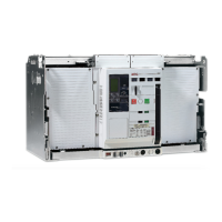
Overview of the ME09 Air Circuit Breaker and its compliance with standards.
Details on rated short time withstand current, short circuit ratings, and rated current.
Adapting standard connection modes for fixed and drawout breakers.
Description of the manual or electrical stored energy mechanism.
Front panel button for electrically closing the breaker.
Adapting standard connection modes for fixed and drawout breakers.
Details on power-rated auxiliary contacts.
Standard interlocking features to prevent incorrect operations.
Indicators showing main contacts, spring charge, and draw-out position.
Optional feature to prevent mismatching breakers and cassettes.
Mechanism for safe disconnection/withdrawal without opening the door.
Devices for securing the breaker and cassette with padlocks.
Padlock facilities for ON/OFF pushbuttons to prevent unauthorized access.
Kits for using Ronis, Profalux, or Castell key locks.
Lockable safety shutters supplied with all cassettes.
Optional contacts for local or remote indication of breaker status.
Optional device for handling and lifting the breaker.
Optional covers providing IP54 protection rating for the breaker.
Records the cumulative number of breaker closing operations.
Devices for interlocking two or three ME09 breakers.
Contact indicating breaker trip due to protective functions.
Indication contacts for spring charge and readiness for closing.
Instructions for storing circuit breakers and cassettes.
Overview of data presented on the breaker's front label.
List of hand tools required for installation, operation, and maintenance.
Explanation of symbols used in the terminal block diagrams.
Definitions of common abbreviations used in wiring diagrams.
Allocation of terminals to accessories and their definitions.
Wiring schematic for Terminal Block A.
Wiring schematic for Terminal Block B.
Note indicating connections to the Trip Unit.
Wiring schematic for Terminal Block A.
Wiring schematic for Terminal Block B.
Note indicating connections to the Trip Unit.
Information on standard and optional wiring diagrams.
Explanation of symbols used in the terminal block diagrams.
Wiring diagram for Ready to Close (RTC) function.
Wiring diagram for command closing coil.
Standard wiring schematic for Terminal Block B.
Wiring for optional trip unit indication contacts.
Wiring for cassette position indication contacts.
User-defined circuits and indicators for breaker status.
Ensure only qualified personnel install, operate, service and maintain equipment.
Specifies environmental conditions for operation and storage.
Details performance characteristics based on IEC 60947-2 standards.
Specifies mechanical and electrical endurance ratings according to IEC 60947.
Caution to always use circuit breaker and accessories within their designated ratings.
Steps for inspecting the shipping container and unpacking the breaker.
Instructions for using lifting trucks and adapters for handling the breaker.
Steps for installing a fixed-pattern circuit breaker.
Procedures for installing drawout type circuit breakers into cassettes.
Ensure breaker is tripped, OFF, and springs discharged before withdrawal.
Steps to safely remove the breaker from its cassette.
Procedures for mounting the breaker into the cassette.
Caution regarding operation of components when approaching TEST position.
Instruction to remove and store the racking handle.
Indicates the breaker is ready for operation after installation.
Description of secondary disconnect terminal blocks for connection.
Details for ordering spare terminal blocks.
Reference to next page for terminal schematics and usage.
Allocation of terminals to accessories and their definitions.
Manual or electrical charging of main springs for breaker operation.
Table detailing the sequence of operation based on indicator states.
Conditions and methods for closing the circuit breaker.
Notice regarding automatic spring charging during closing operation initialization.
Various methods for opening (tripping) the circuit breaker.
Ensure breaker is tripped, OFF, and springs discharged before withdrawal.
Preparation and steps for withdrawing the circuit breaker.
Considerations for current transformers during breaker withdrawal.
Procedure for discharging springs when using a motor operator.
Steps for operating the racking mechanism.
Preparation and steps for inserting the breaker into the cassette.
Instruction to remove and store the racking handle.
Table showing operating positions and corresponding functions.
General information about the Mpro Trip Unit and its functions.
Safety warning about breaker tripping and spring discharge.
List of abbreviations and acronyms used in the manual.
Table of abbreviations and their descriptions.
Description of the trip unit's graphical LCD and interface.
How to navigate and use the LCD interface with function keys.
Electrical requirements for installing the trip unit.
Interfaces between trip units and breaker/cassette connections.
Details on Modbus communication protocol support and settings.
Description of overcurrent protection functions like LT, ST, and Instantaneous.
Manual reset configuration, interlocking with mechanical lockout.
Manual reset configuration, interlocking with mechanical lockout.
Automatic reset configuration, disabling manual reset button.
Interface options like LCD, touchpad, multilingual, and reset modes.
Settings for Long Time Pickup and Overload Current Protection.
Settings for Short Time Pickup and Short Circuit Current Protection.
Protection settings for ground and earth faults.
Parameters measured by the unit, including voltage, current, power.
Overcurrent, undervoltage, and overvoltage protective relay functions.
Functions for data acquisition, diagnostics, and event logging.
Other features like ZSI, communication, and power supply.
Information about the trip unit's internal battery and its limitations.
Instructions for proper disposal of batteries according to regulations.
Overview of the four operating modes: Setup, Meter, Status, Events.
Programming the trip unit using the SETUP mode.
Steps for entering and storing set points into the trip unit's memory.
How ZSI interlocks coordinate fault reactions.
ZSI function operates with series-connected breakers and requires +24VDC.
Effect of ZSI input on upstream breaker settings.
Details on Modbus communication protocol support and settings.
Table of input assignments for communication parameters.
Table of group assignments for relay functions.
List of available neutral protection options.
How neutral setting influences other protection devices.
Setting for Ground Fault Sum protection.
Setting for Reduced Instantaneous Trip.
Setting for Short Time ZSI protection.
Setting for Ground Fault ZSI protection.
Setting for Instantaneous trip protection.
Setting for PT connection type.
Setting for PT voltage.
Setting for Modbus slave address.
Setting the date for the trip unit.
Setting the time for the trip unit.
Setting the display language.
Setting a password for access.
Settings for Long Time Pickup and Overload Current Protection.
Settings for Short Time Pickup and Short Circuit Current Protection.
Setting for Instantaneous trip protection.
Setting for Ground Fault Sum protection.
Setting for Reduced Instantaneous Trip.
Setting for Short Time ZSI protection.
Setting for Ground Fault ZSI protection.
Setting for PT connection type.
Setting for PT voltage.
Setting for Modbus communication baud rate.
Configuration for Relay 1 output.
Configuration for Relay 2 output.
Accessing and indicating electrical parameters of the circuit.
Measurements and indications of current, voltage, power, etc.
Note on energy reset support via software or communications.
Table listing measured parameters, units, and phases.
Option to return to the METER display.
The trip unit logs the last 10 events with details like current and phase.
Option to return to the METER display.
List of communication parameters and their values.
List of communication parameters and their values.
List of communication parameters and their values.
List of communication parameters and their values.
List of communication parameters and their values.
List of communication parameters and their values.
Overview of the digital electronic trip unit and its features.
Steps for installing the trip unit onto the PMU base.
Connection diagrams for Mpro-S and Mpro-N electronic trip units.
List of abbreviations used in connection schemes.
List of abbreviations used in connection schemes.
Ensure breaker is tripped and springs discharged before installing locks.
Caution to always use circuit breaker and accessories within their designated ratings.
Security padlocking for the breaker front panel.
Padlocking feature on the front panel to lock breaker contacts open.
Steps to engage the padlocking device and place padlocks.
Padlocking to secure the shutter and prevent access to main contacts.
Steps to remove breaker, locate levers, and open shutters.
Security locking of shutters and racking handle entry when breaker is DISCONNECTED.
How to apply padlocks for shutter and handle access security.
Step to ensure breaker is in DISCONNECTED position before locking.
Step to remove the racking handle.
Step to pull the locking bar and expose the locking eye.
Step to turn the racking handle shutter drive clockwise.
Expected condition after engaging the locking feature.
Step to check if shutter plate movement is prevented.
Interlock type for two breakers with no priority.
Interlock type for three breakers with no priority.
Interlock type for three breakers, one always OFF.
Interlock type for three breakers with priority settings.
Interlock type for two breakers with no priority.
Interlock type for three breakers with no priority.
Interlock type for three breakers, two can be closed.
Interlock type for three breakers with priority settings.
Description of locking functions for breakers.
Types and quantities of locking devices available.
Specific details about the locking devices.
| Brand | AEG |
|---|---|
| Model | ME09 |
| Category | Circuit breakers |
| Language | English |