ᆅჾ
ۉጱྃഗ
֪
য়ߢ༵๖ణ
INTRO
TRIP UNIT
LOCKS ACCESSORIES TESTS APPENDIX
1.3-03
ᆅჾࡀ߭Ҿጎ֡ፕۉጱྃഗ
ୟഗ
BREAKER
NF1:ဣଚگუഘୟഗ
2/4/2!༵ืࢅҾጎ
๑ᆩ༵ืכࢅದഗጎዃLjᆩᇀᅎۯୟഗăದ
ഗᆩᇀᅎۯ!4!႙ୟഗă
2/4/3!ࠦۨ๕ୟഗҾጎ
2/! ඓԍୟഗฉݛᆶፁࠕڦဤLjᅜՍָأ௶ࢷቸLjֱ
௶ࢷةۅă
3/!๑ᆩ!5!߲!N9!அພᅜ!36!On!ڦ౦ୟഗࠦۨڟ
ࢇڦኧࠓฉă
4/!ୟഗᅃ֨Քᆶൣညڦথںۅă
2/4/4!؏๕ୟഗҾጎ
؏๕ୟഗཚᅜҾጎڟ؏ฉڦႚ๕ă
2/!Ӏቷ!2/5!বዐຎڦ؏ײႾୟഗٗ؏ዐൽă
3/! ߵᄲ൱؏ࠦۨሞದۉಎฉă؏ᅜᆩ༵ืLj
ڍසࡕ๑ᆩ༵ืכഄ༵ืጎዃLj൩๑ᆩ࿋ᇀ؏ኟ
௬ࢅԝ௬ڦඇև
5!߲༵ืă
4/! ؏ࠦۨڟ࿋Ljথᆅࢅᆅڦۉમ0జಇăথ
జಇ้Ljඓԍ؏ࢫ௬ڦೋֶ0ᆌ૰ྺፌၭă
5/!๑ᆩ!5!߲!N9!அພᅜ!36!On!ڦ౦؏Ҿጎڟኟ
௬ࢅԝ௬Ҿጎۅฉă
6/!ֱҾጎǖ
..!ඓԍ؏ڹፗೝ།Ljྺኟݛႚă
..!ඓԍҾඇڔӱᅜሞҾጎஅພྜඇౣࢫጲᆯᅎۯă
7/!Ӏቷ!2/5!বዐڦຫ߸࣑؏ాڦยԢă
8/!Ⴔᄲ้Lj؏ଇ֨Քᆶൣညڦথںۅă
1.3 INSTALLATION
Using a LiŌing Truck and Adapter OpƟonally available to
facilitate breakers handling. an adapter being available
allowing one to use the same device for envelope 3 devices.
1.3.2 Fixed Circuit Breaker InstallaƟon
1. Ensure adequate clearance above the circuit breaker to
allow removal of the arc chutes and inspecƟon of the arcing
contacts.
2. Fasten the circuit breaker into posiƟon on a suitable support
structure using four M8 bolts, torque to 25 N m.
3. A clearly marked grounding point is provided on either side
of the circuit breaker.
1.3.3 Drawout Circuit Breaker InstallaƟon
Drawout type circuit breakers are normallydelivered already
mounted in casseƩes.
1. Remove the circuit breaker from its casseƩe using
withdrawal procedures described in SecƟon 1.4.
2. PosiƟon the casseƩe as required in the switchboard. The
casseƩe may be liŌed by hand; however, if a handling truck or
other liŌing gear is used, use all four liŌing holes provided at
front and rear of the casseƩe.
3. PosiƟon casseƩe in place and connect incoming and
outgoing cables/busbars. Ensure there is minimal
deŇecƟon/stress to the back of the casseƩe when connecƟng
busbars.
4. Mount the casseƩe using four M8 bolts andtorque to 25 N m
at the front and rear mounƟng points.
5. Check the mounƟng to:
-- Ensure the casseƩe base is Ňat and the frame is square.
-- Ensure the safety shuƩers move freely aŌer the mounƟng
bolts have been fully Ɵghtened.
6. Replace the Device in the casseƩe as described in secƟon
1.4.
7. If needed, a clearly marked grounding point is provided on
both sides of the casseƩ
e.
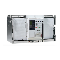
!2/4ǖդ࿋ዃ
Gjh/!2/4;!Iboe!Hsjq!Mpdbujpo
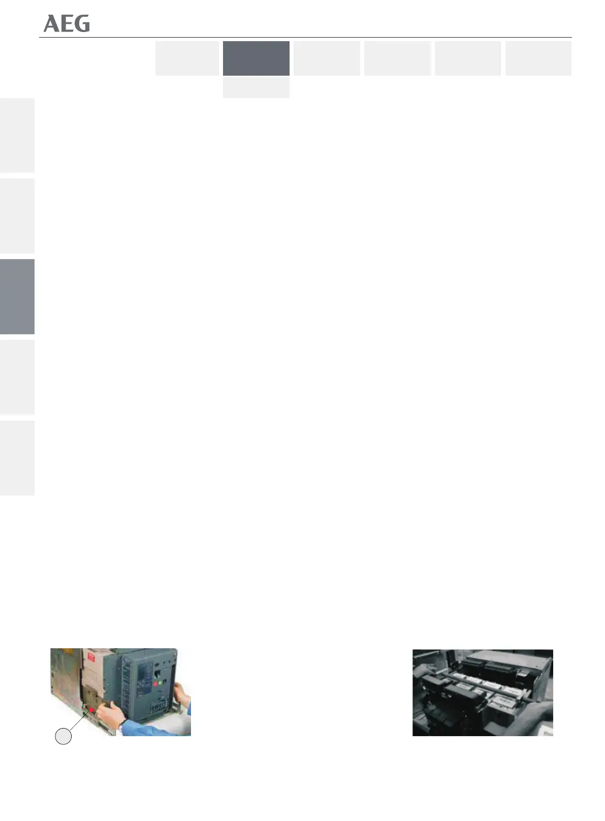
!2/5ǖ༵ืۗܺ
Gjh/!2/5;!Mjgujoh!Fzft
$