Installed in all Trip Units types the second SETUP mode display is
always the Short Time Pickup set point. The Short Time Pickup
funcƟon establishes the current at which a Ɵmed short Ɵme trip
is acƟvated (Ist) and is adjusted in funcƟon of the Long Time
Pickup seƫng Ir. The choices of pickup seƫngs are from 1.5 to
12.0 (1) Ɵmes the long Ɵme seƫng, xLT ( Ir) , in steps of 0.5 xLT
(Ir). see table 2.5. The ST pickup value (Ist) tolerance band is
-10% to +10% of the set point. An addiƟonal accuracy
degradaƟon of ±5% occurs when waveforms with signiĮcant
harmonic distorƟon are present.
TheMpro type S and N trip unit types oīer 22 long Ɵme delay
bands that have a shape similar to that of the thermal element
of a thermal magneƟc circuit breaker.
The minimum and maximum delay Ɵmes and their IEC 947
classiĮcaƟon are indicated in table 2.3. The bands are depicted
as Time Current Diagram in appendix 6.1 of this ApplicaƟon
manual.
Installed in all Trip Units types the Įrst SETUP mode display is
always the Long Time Pickup setpoint. This set point establishes
the breaker's ampere raƟng Ir.
The 1st screen allows the user to deĮne up to 6 diīerent user
currents Ie that can be set as a fracƟon of 1, 0.98, 0.97, 0.96,0.45
or 0.4 x the breaker current raƟng In. These are indicated as a
current value on the screen
The deĮnite current seƫng Ir is set on the 2nd LT seƫng screen
as a fracƟon of the user current value Ie. (xLT = LT mulƟplier x Ie).
Their are 11 Long Time Pickup seƫngs ranging from are 0.50 to
1.00 Ɵmes x CT in steps of 0.05. The pickup value is set at a value
of approximately 1.12 x the seƫng with a tolerance of -10% to
+10%. An addiƟonal accuracy degradaƟon of ±5% occurs when
waveforms with signiĮcant harmonic distorƟon are present.
(For an overview of all available seƫngs see table 2.4 on page
2-12)
2.2.3.1 ้๔ۯۉୁDŽࡗሜԍࢺยዃDžIr
2.2.3.1 Long Time Pickup (Overload ProtecƟon seƫng) Ir
2.2.3.1.1 Long Time Delay (On overload ProtecƟon) LTD
2.2.3.2 Short Time Pickup (Delayed Short Circuit ProtecƟon) ST
2.2.3.1.1 ჽ้DŽࡗሜԍࢺDžLTD
2.2.3.2 ܌้๔ۯۉୁDŽჽ้܌ୟԍࢺDžST
!2.3ǖ߲߳ۨڦ!LTD!ݔྷዐኸۨࡗሜڪူࡗሜཌቄ้DŽڇ࿋ྺ௱Dž
Ҿጎሞᆶૌ႙ڦۉጱྃഗዐLjڼᅃ߲!TFUVQDŽยዃDž
ఇ๕၂๖๔ዕ!Mpoh!Ujnf!QjdlvqDŽ้๔ۯۉୁDž
ยዃۅăᅜሞยዃۅยۨୟഗܮۨۉୁ!Jsă
ᆩࢽᅜሞڼᅃ߲၂๖ೡฉፌܠยۨ! 7! ߲փ! ཞڦᆩࢽۉ
ୁ! JfLjยዃྺݴ๕! 2Ă1/:9Ă! 1/:8Ă1/:7Ă1/56! !
1/5!y!ୟഗۉୁܮۨኵ!JoLjኄၵݴ๕ሞ၂๖ೡฉ၂๖ྺ
ۉୁኵă
ඓۨڦۉୁยዃ! Js! ሞڼܾ߲!MU! ยዃ၂๖ೡฉยዃLjย
ዃྺᆩࢽۉୁኵ!Jf!ڦݴ๕ăDŽyMU!>!MU!ဣຕ!y!JfDžă
ᆶ!22!้߲๔ۯۉୁยዃLjݔྷྺ!1/61ڟ!2/11!y!DU
DŽօྺ!1/16Džă
๔ۯۉୁኵยዃྺሀڪᇀ!2/23!y!ยዃኵLjࠅֶྺ!.21&!
ڟ! ,21&ăհႚ٪ሞჹዘڦၿհ฿ኈ้Ljඓ܈ᅜምই
گ! Ġ6&DŽᆶ࠲ᆶᆩยዃڦ߁ຎLj൩֖ڼ! 3.23! ᄻ
ฉڦ3/5Džă
Nqsp!T-O႙ۉጱྃഗᆶ!33!߲ჽ้ݔྷLjྔႚᇑඤ
ىୟഗڦඤᇮૌຼă
!3/4!ଚକፌ܌ࢅፌڦჽ้ഄ!JFD!:58ݴૌăԨᆌ
ᆩ֩!7/2!ዐݔྷࣼྺ้ۉୁă
Ҿጎሞᆶૌ႙ڦۉጱྃഗዐLjڼܾ߲!SETUPDŽยዃDž
ఇ๕၂๖๔ዕ! Tipsu! Ujnf! QjdlvqDŽ܌้๔ۯۉୁDž
ยዃۅă܌้๔ۯࠀీยۨۉୁኵLjٳڟۉୁኵ้Ljۨ
้܌้ཌቄഐۯ! )Jtu*Ljยዃኵߵ้๔ۯۉୁยዃ!
Js! ႜۙবă๔ۯۉୁยዃኵڦስݔྷྺ! 2/6!ڟ!23/1!
)2*! ױᅜ้ยዃኵLjyMU! )Js*Ljօྺ! 1/6! y! MU!
)Js*ă֖!3/6ă
TU! ๔ۯۉୁኵ! )Jtu*! ࠅֶݔྷྺยዃۅڦ! .21&! ڟ!
,21&ăհႚ٪ሞჹዘڦၿհ฿ኈ้Ljඓ܈ᅜምইگ!
Ġ6&ă
2.2-02
NF1:ဣଚگუഘୟഗ
ຫׂ֡ፕ၂๖ೡఇ๕൸၍٪ഗҾጎথ၍
ୟഗ
֪
BREAKER LOCKS ACCESSORIES TESTS APPENDIX
ᆅჾ
ۉጱྃഗ
INTRO
TRIP UNIT
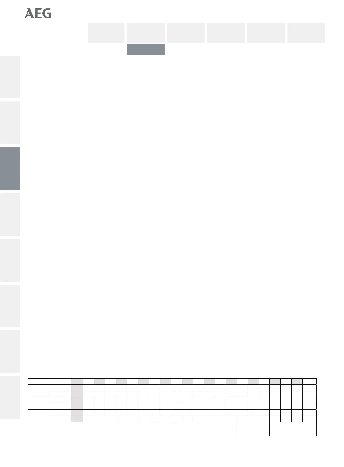
Table 2.3 : Overload Tripping Ɵmes at indicated overload levels per selected LTD band , in Seconds.
Ir C-2 C-3 C-4 C-5 C-6 C-7 C-8 C-9 C-10 C-11 C-12 C-13 C-14 C-15 C-16 C-17 C-18 C-19 C-20 C-21 Cmax
ፌ 7.8 23.4 46.7 62.3 93.4 125 156 187 218 249 280 311 374 436 498 560 623 685 747 810 872 934
ፌ܌ 4.0 12.0 24.0 32.0 48.0 64.1 80.1 96.1 112 128 144 160 192 224 256 288 320 352 384 416 448 480
ፌ 1.3 3.86 7.73 10.3 15.5 20.6 25.8 30.9 36.1 41.2 46.4 51.5 61.8 72.1 82.4 92.7 103 113 124 134 144 155
ፌ܌ 0.80 2.41 4.82 6.43 9.64 12.9 16.1 19.3 22.5 25.7 28.9 32.1 38.6 45.0 51.4 57.8 64.3 70.7 77.1 83.
6 90.0 96.4
x
1.5
3
7.2
ፌ 0.21 0.62 1.24 1.66 2.49 3.32 4.15 4.98 5.81 6.64 7.47 8.30 9.96 11.6 13.3 14.9 16.6 18.3 19.9 21.6 23.2 24.9
ፌ܌ 0.13 0.40 0.81 1.07 1.61 2.15 2.69 3.22 3.76 4.30 4.83 5.37 6.45 7.52 8.60 9.67 10.7 11.8 12.9 14.0 15.0 16.1
ۉݞࢺڪޙࢇ!
!
10b 10 20 30 40
Cmin
Motor ProtecƟon Class to IEC 947-4