2.6-01
NF1:ဣଚگუഘୟഗ
ຫׂ֡ፕ၂๖ೡఇ๕൸၍٪ഗҾጎথ၍
ୟഗ
֪
BREAKER LOCKS ACCESSORIES TESTS APPENDIX
ᆅჾ
ۉጱྃഗ
INTRO
TRIP UNIT
2.6 Ҿጎ
ᄲຫ
ᆶ! NF1:! ഘୟഗದᆶຕጴۉጱۉጱྃഗLjۉጱ
ྃഗᆶ!T!ࢅ!O!ଇዖԨ႙ࡽă
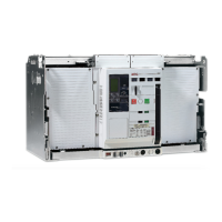
ܾዖ႙ࡽᆶ၎ཞڦยLjದᆶ၂๖ೡLj༵ࠃۉୁLjཚ
ࡗڇጚඓڦ֓ڇ֡ፕᅜሞ࠽ݘڦۉୁݔྷాۙবୟ
ഗ֖ຕă
๑ᆩ! 5! ߲ยዃࢅᅃ߲ඓණཚࡗ֓ڇኴႜᆶࠀీLj
ܸٗీࠕጚඓںยዃጎዃă
ۉጱྃഗҾጎ
2/ୟഗ௬ӱፇฉڦ!7!߲அۤDŽ!BDžLjൽူ௬ӱă
3/Nqsp!ۉጱྃഗҾጎሞ!QNV!ፗฉLjස!C!๖ă
Ӏቷ๖ݛ݆Ӏူ߇Ljܔዐۉጱྃഗă
4/ۉጱྃഗ౧ኟඓ֭!QNV!ፗాLjස!D!๖ă
5/ኟඓ֭ۉጱྃഗࢫݣ߇Ljኄᄣࣷۉጱྃ
ഗۨሞ!QNV!ፗዐLjස!E!๖ă
6/ࢫҾጎമ௬ӱă
Short descripƟon
All the ME09 power circuit breakers are equipped with a digital
electronic trip unit available in two basics versions S&N.
Each has a common design that comes with a screen providing
an ammeter and following a simple and accurate menu driven
adjustment of the breaker parameters across a board current
range.
All the funcƟonality is menu driven by using 4 seƫng and one
enter key thus allowing a fast and accurate seƫng of device.
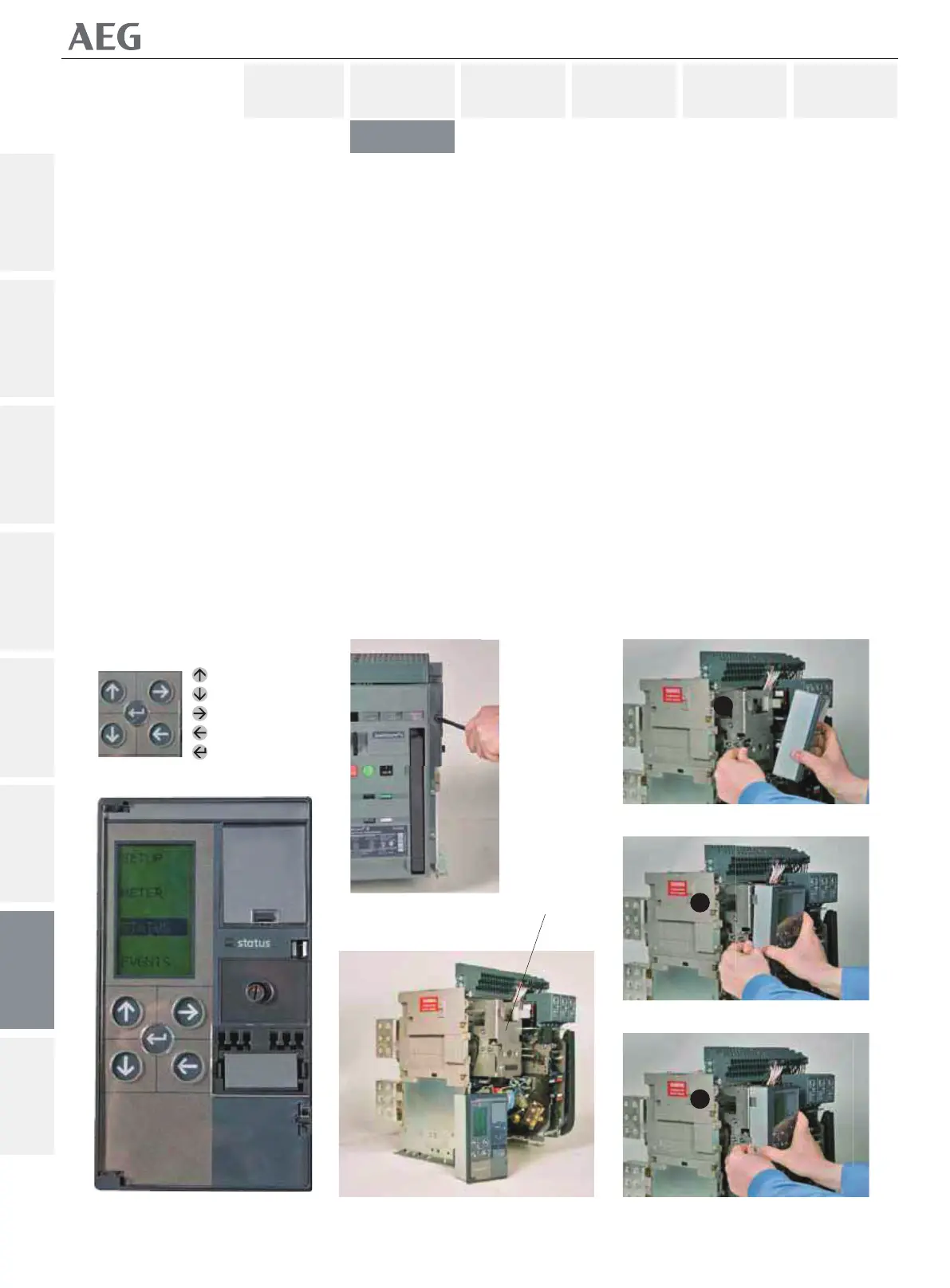
TRIP UNIT INSTALLATION
1. Loosen the 6 screws (Fig. A) on the breaker fascia assembly
and remove the fascia
2. Mpro Trip unit is mounted on PMU base as shown in Fig. B.
Press the lever and align the trip unit as shown.
3. Insert the trip unit knob into the PMU base properly as shown
in Fig. C
4. Release the lever once the trip unit is insert properly, thus the
release of lever will lock the trip unit to the PMU base as per Fig. D
5. Then install the front cover.
2.6 INSTALLATION
ၠฉ
ၠᆸDŽူᅃ߲Dž
ၠူ
ၠፑDŽฉᅃ߲Dž
ඓණDŽԍ٪Dž
Ӏ
A
B
B
C
D
[PMU]