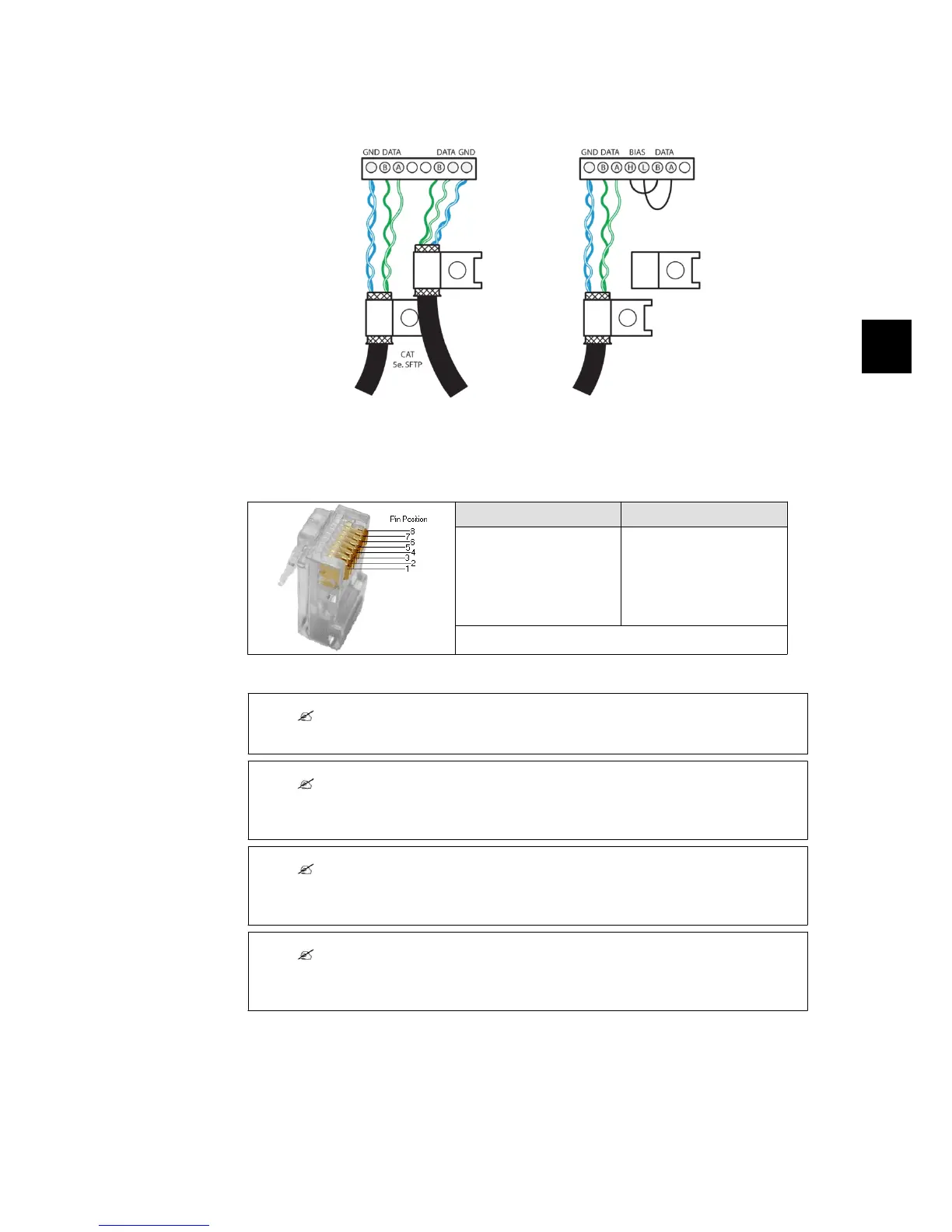
5.1.4. RS485 Communication Board Connections
Illustration 5.7: RS485 Detail of Communication Board.
BIAS L and Bias H are to be connected to RX/TX B and RX/TX A respectively for termination of
RS485 bus.
Pinout RS-485 Pinout Ethernet only, via the
RJ45 connector
1. GND 1. RX+
2. GND 2. RX
3. RX/TX A (-) 3. TX+
4. BIAS L 4.
5. BIAS H 5.
6. RX/TX B (+) 6. TX-
7. Not connected 7.
8. Not connected 8.
Bold = Compulsory, Cat5 cable contains all 8 wires
For Ethernet: 10Base-TX and 100Base-TX auto cross over
Table 5.10: RJ45 Pinout Detail
Note:
The RS485 communication bus must be terminated at both cable ends.
Note:
The two network types cannot be mixed. The inverters can only be connected in networks
which are either solely RS485 or solely Ethernet.
Note:
Each inverter has a unique RS485 address when it is delivered. This address is defined at the
time of production.
Note:
Ethernet connection is recommended for faster communication.
RS485 connection is required when a web logger or data logger is connected to the inverter.
5. Technical Data
8000038781_00_BAL_en / L00410564-01_02 31
5

 Loading...