Do you have a question about the AEM Performance Electronics 30-3300 and is the answer not in the manual?
Product has legal restrictions; must be used in compliance with laws.
Improper installation can cause major engine/vehicle damage; seek professional help.
Recommends not exceeding 50% methanol concentration due to safety risks.
Describes methanol as toxic, flammable, and hazardous if absorbed through skin.
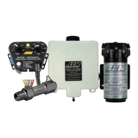
Lists key features: 1.15-gallon tank, 200 PSI pump, progressive controller.
Visual guide showing component connections for the injection system.
Controller must be inside the vehicle, not waterproof.
Mount tank below injection point to prevent fluid leakage into intake tract.
Select location near and below tank, fasten securely.
Mount controller inside cabin, connect wiring per diagram.
Fill tank with water, use TEST button to flush system before installing nozzle.
Connect nozzle to hose, test system with water.
Verify system operation, check for leaks, use desired fluid.
Mount nozzle above tank, before throttle plate, after MAF/intercoolers.
Engine tuning is required for optimal power gain with the system.
Tank must be below injection point; pump near tank and at or below fluid level.
Instructions for mounting the 1.15-gallon tank, emphasizing correct orientation and hardware.
Guidelines for installing an optional 5-gallon tank, stressing proper mounting.
Mount controller inside driver's compartment; use appropriate gauge wire.
Details pin assignments, wire gauges, colors, and connections for the controller.
Guidance on mounting the external LED and connecting it to indicate system status.
Instructions for connecting the boost pressure hose to the manifold.
Steps to flush the tank and lines with water using the TEST button.
Chart to select the appropriate atomizing pintle based on horsepower and boost level.
Visual guide to identify the 250cc, 500cc, and 1000cc pintles by head and stem.
Mount nozzle higher than tank, before throttle plate, after MAF and intercoolers.
Use TEST button to check pump operation, flow, and for leaks.
Only water and methanol are supported; never use hydrocarbon fuels.
Lists error codes, descriptions, controller status, and recommended actions for system faults.
Guides users through diagnosing issues based on LED flash codes and error types.
Explains how boost affects fluid injection and the function of the Start/Full PSI knobs.
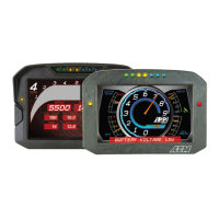
Describes the function of the on-board Status LED for indicating operation and errors.
Location and type of fuse for the controller, importance for pump operation.
How to use the TEST button to verify system functionality without fluid in the engine.
Explains the pump driver's short circuit protection modes and how to enable/disable them.
Compares AEM's linear flow output to competitors' non-linear output.
How Boost-Safe output activates on fluid loss or error to protect the engine.
Connects to a solenoid activated when the system pumps fluid.
How to configure the controller for non-progressive, full-on operation.
Importance of tuning for aggressive tunes and maximizing power with the system.
How to set base AFR, adjust injection flow rate via nozzle or PSI settings.
Table showing freezing points for different water/methanol mixture concentrations.
Instructions for periodic cleaning of the injector nozzle.
Monitors flow, triggers alarms for deviations, PC programmable for safety.
Displays real-time flow rate data; filter recommended with gauge.
Micronic filter to remove particles, enhances system longevity.
Kit includes extra nozzles and hardware for a second nozzle installation.
Larger capacity tank for increased fluid holding.
Covers defects in material/workmanship for 12 months, limited to repair/replacement.
Voids warranty for improper use, installation, accident, abuse, or unauthorized alterations.
Procedure for warranty claims, requiring tech line contact and RMA number.
| Brand | AEM Performance Electronics |
|---|---|
| Model | 30-3300 |
| Category | Automobile Accessories |
| Language | English |