Page 8
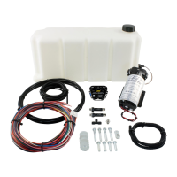
Progressive Controller Installation
Connect to ground (black) wire of pump.
Connect to ground (black) wire of external LED.
Connect to positive (red) wire of external LED.
1.5A Low Side output. Connect to optional flow control
solenoid.
1.7A Low Side output. Grounded when error condition
exists.
Connect to the positive (red) wire of pump.
Main ground connection, connect directly to battery
ground.
Connect to the white wire of the fluid tank level sensor*
Connect to the black wire of the fluid tank level sensor*
Arms injection system. Connect to a switched 12V
source.
Connect to External Signal. (0-5V, injector duty, MAF
frequency)
Main Power Connection, connect directly to positive
battery terminal.
*Note: If fluid tank is equipped with previous generation level sensor, identified by having two black wires, then
pins 8 (white) and 9 (brown) may be connected to either of the two black sensor wires. The polarity is
unimportant.
**Note: If you need to extend the wires to mount the controller use at least 16 AWG wire for the pump and
controller ground circuits and 18 AWG for the remainder.
External LED Install
Find a suitable location in the driver’s line of sight to mount the external LED. Mount the LED
and run the wires to the controller. The LED indicates the operation of the controller. If the
pump is off and there are no errors the LED will be off. If there are no errors and the pump is on
the LED intensity will vary with the pump speed. If there are any errors they will be indicated by
flashing the LED.