MAINTENANCE
Chapter 7 - MAINTENANCE
7.1 MAINTENANCE SCHEDULE
The unit requires regular routine maintenance to
keep up efficiency and reliability. For best
operation and life of the unit, the following
routine maintenance procedures should be
carried out in the time periods specified.
See Appendix I for complete CSD-1
inspection check list
WARNING!
TO AVOID PERSONAL INJURY, BEFORE
SERVICING:
(A) DISCONNECT THE AC SUPPLY BY
TURNING OFF THE SERVICE SWITCH
AND AC SUPPLY CIRCUIT BREAKER
(B) SHUT OFF THE GAS SUPPLY AT THE
MANUAL SHUT-OFF VALVE PROVIDED
WITH THE UNIT
(C) ALLOW THE UNIT TO COOL TO A
SAFE TEMPERATURE TO PREVENT
BURNING OR SCALDING
7.2 SPARK IGNITOR
The spark ignitor assembly is located in the
body of the burner (see Fig. 7.1A). The ignitor
may be HOT. Care should be exercised. It is
easier to remove the ignitor from the unit after
the unit has cooled to room temperature.
To inspect/replace the Ignitor:
1. Put the green ON/OFF button on the control
panel, to the OFF position and disconnect
AC power to the unit.
2. Remove the rear, side and top panels from
the unit.
3. Disconnect the ignitor cable from the ignitor
contactor and unscrew the ignitor bushing
from the burner shell.
4. Insert the ignitor removal tool into the burner
shell, where the ignitor bushing was
removed. Fit the hexagonal end of the tool
over the ignitor. (See Fig. 7.1B) Unscrew the
ignitor from the burner head. Remove the
ignitor from the burner shell, by grasping the
contact end of the ignitor.
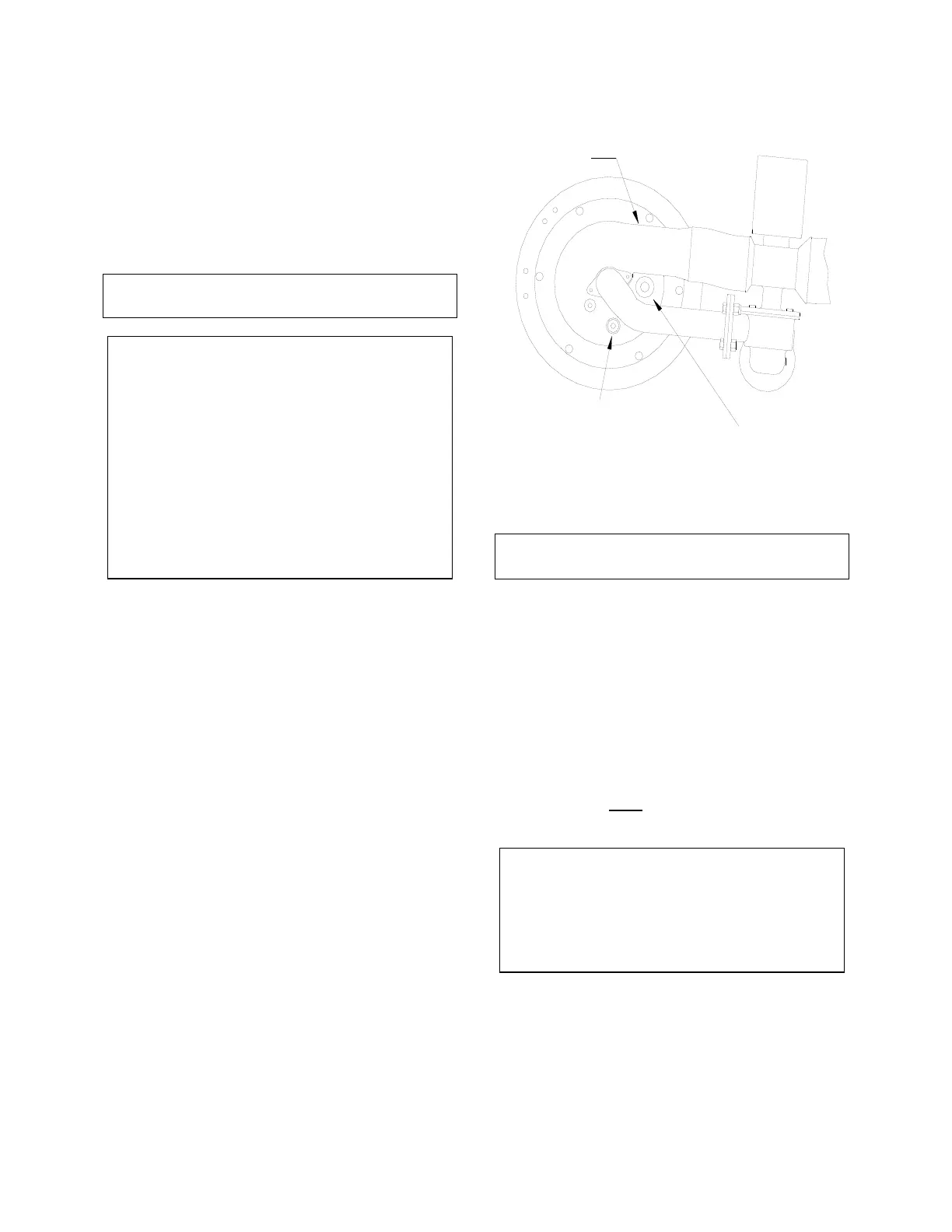
Figure 7.1A
Spark Ignitor and Flame Detector Location
Top View
CAUTION!
The ignitor may be hot
5. The ignitor is gapped at 1/8-inch. If there is a
substantial erosion of the spark gap or
ground electrode, the ignitor should be
replaced. If carbon build-up is present, clean
the ignitor using fine emery cloth. Repeated
carbon build-up on the ignitor is an
indication that a check of the combustion
settings is required (see Sections 4.2 and
4.3 for Combustion Calibration).
6. Prior to reinstalling the ignitor, an anti-seize
compound must
be applied to the ignitor
threads.
CAUTION!
The ignitor must be removed and installed
using the ignitor removal tool provided with
the unit(s). Damage to the burner due to
using a socket for removal and installation
of the ignitor is not covered under warranty.
7. Reinstall the ignitor using the ignitor removal
tool. Do not over tighten the ignitor. A slight
snugging up is sufficient. Reinstall the ignitor
contactor (hand tight only) and reconnect
the ignitor cable.
8. Install the side and top panels on the unit.
BURNER
FLAME DETECTOR
IGNITOR CONTACTOR

 Loading...


