SAFETY DEVICE TESTING
Figure 6.7
Air/Fuel Valve Cover Screw Locations
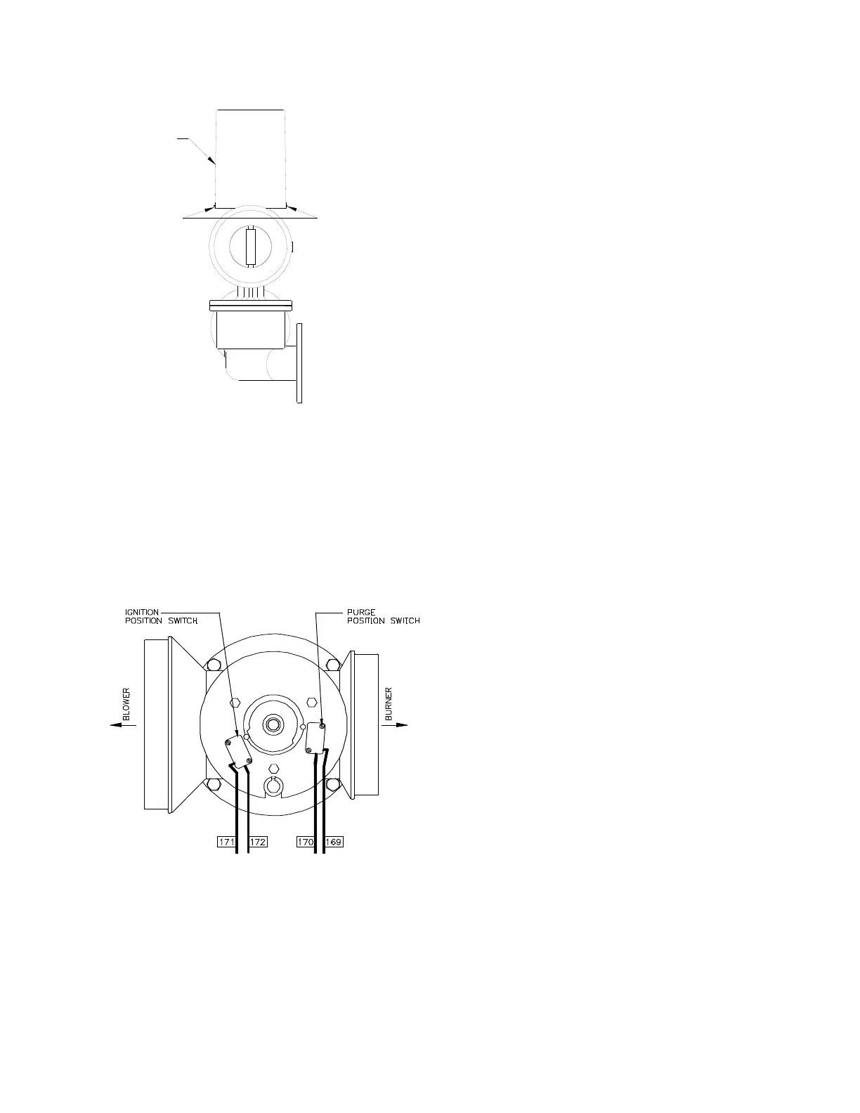
9. Disconnect wire #172 from the air/fuel valve
purge position switch. This is the switch
closest to the blower (See Fig. 6.8).
10. Restore AC power to the unit.
11. Start the unit.
Figure 6.8
Air/Fuel Valve Purge Position and Ignition
Switch Locations
12. The unit should shutdown and displays the
message “LOCKOUT RUN”.
12. Disconnect AC power from the unit.
13. Reconnect wire #172 to the air/fuel valve
purge position switch.
14. Disconnect wire #170 from the ignition
position switch. This is the switch closest to
the blower of the unit (See Fig. 6.8).
15. Restore AC power to the unit, and reset the
combustion safeguard.
16. Start the unit in manual mode.
17. The unit should lockout and display the
message “FLAME FAULT DURING IGN
TRIAL”.
18. Disconnect AC power from the unit.
19. Reconnect wire #170 to the ignition position
switch.
20. Replace the air/fuel valve cover.
21. Restore AC power to the unit.
22. Set the unit to auto mode to resume normal
operation.
6.8 SAFETY PRESSURE RELIEF VALVE
TEST
Test the safety Pressure Relief Valve in
accordance with ASME Boiler and Pressure
Vessel Code, Section VI.
VALVE COVER
COVER SCREWS
(3-120° APART)

 Loading...


