EasyManua.ls Logo

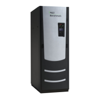
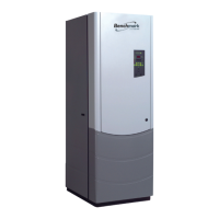
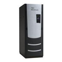
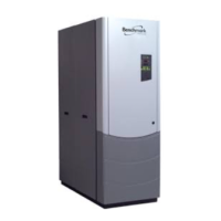
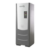
Aerco BENCHMARK 6000 User Manual

Aerco BENCHMARK 6000
210 pages
To Next Page IconTo Next Page
Page #1 background imageLoading...
Page #1 background image
Benchmark 6000 Boiler Installation, Operation & Maintenance Manual
OMM-0086_0D AERCO International, Inc. 100 Oritani Dr. Blauvelt, NY 10913 Page 1 of 210
GF-133 Ph.: 800-526-0288 03/20/14
BENCHMARK 6000
Gas-Fired Boiler
USER MANUAL
Installation, Operation and Maintenance
Natural Gas Modulating &
Condensing Hot Water Boiler
Applicable to Serial Numbers:
N-14-0172 and Above
Latest Update: 03/20/14

Table of Contents

Question and Answer IconNeed help?

Do you have a question about the Aerco BENCHMARK 6000 and is the answer not in the manual?

Aerco BENCHMARK 6000 Specifications

General IconGeneral
ModelBENCHMARK 6000
TypeCondensing Boiler
Input BTU/hr6, 000, 000 BTU/hr
Fuel TypeNatural Gas or Propane
Heat ExchangerStainless Steel
Operating Pressure160 psi
Input Capacity6, 000, 000 BTU/hr
Vent Diameter6"

Summary

CHAPTER 1. SAFETY PRECAUTIONS

1.1 WARNINGS & CAUTIONS

General safety regulations, warnings, and cautions for installers and operating personnel.

1.2 EMERGENCY SHUTDOWN

Procedure for emergency shutdown of the boiler in case of overheating or gas supply failure.

CHAPTER 2. INSTALLATION

2.9 AC ELECTRICAL POWER WIRING

Guidance on connecting AC power wiring to the unit, referencing GF-2060.

2.9.1 Electrical Power Requirements

Details on available voltage configurations and power box terminal blocks.

2.10 FIELD CONTROL WIRING

Information on factory-wired internal control systems and external control features.

CHAPTER 3. OPERATION

3.2 CONTROL PANEL DESCRIPTION

Description of the C-More Control Panel, its controls, indicators, and displays.

3.3 CONTROL PANEL MENUS

Overview of the menu structure for setting up and configuring the unit.

3.6 CONFIGURATION MENU

Menu for adjusting internal setpoint and other configuration settings.

3.8 COMBUSTION CAL MENU

Menu for performing combustion calibration to optimize efficiency and emissions.

3.9 BST (BOILER SEQUENCING TECHNOLOGY ) MENU

Menu for configuring, operating, and monitoring the Boiler Sequencing Technology system.

3.10 START SEQUENCE

Checks pre-purge safety switches and initiates the start sequence.

CHAPTER 4. INITIAL START-UP

4.1 INITIAL START-UP REQUIREMENTS

Requirements for initial boiler start-up, including installation, controls, calibration, and testing.

4.2 TOOLS AND INSTRUMENTATION FOR COMBUSTION CALIBRATION

Necessary tools and instrumentation for performing combustion calibration.

4.2.1 Required Tools & Instrumentation

List of tools and instrumentation needed for combustion calibration.

4.3 PILOT IGNITION

Description of the pilot ignition system and its components.

4.4 NATURAL GAS COMBUSTION CALIBRATION

Procedures for calibrating combustion for low and ultra-low NOx emissions.

CHAPTER 5. MODE OF OPERATION

5.2 INDOOR/OUTDOOR RESET MODE

Mode based on outside air temperature to adjust supply header temperature.

5.3 CONSTANT SETPOINT MODE

Mode used for fixed header temperature applications like heat pump loops.

5.4 REMOTE SETPOINT MODES

Mode allowing remote control of setpoint via EMS or BAS using current or voltage signals.

5.5 DIRECT DRIVE MODES

Mode where air/fuel valve position is controlled by a remote signal.

5.6 AERCO CONTROL SYSTEM (ACS)

Mode for operating multiple boilers efficiently using an AERCO Control System.

5.7 COMBINATION CONTROL SYSTEM (CCS)

System using multiple boilers for space heating and domestic hot water needs.

CHAPTER 6. SAFETY DEVICE TESTING

6.1 TESTING OF SAFETY DEVICES

Importance of periodic safety device testing to ensure proper operation and compliance.

6.2 LOW GAS PRESSURE FAULT TESTS

Procedures for testing the low gas pressure fault switch.

6.3 HIGH GAS PRESSURE FAULT TEST

Procedures for simulating and testing the high gas pressure fault.

6.4 LOW WATER LEVEL FAULT TEST

Procedure to simulate and test the low water level fault condition.

6.5 WATER TEMPERATURE FAULT TEST

Procedure to simulate and test the high water temperature fault.

6.6 INTERLOCK TESTS

Tests for the Remote Interlock and Delayed Interlock circuits.

6.6.1 Remote Interlock Test

Procedure for testing the Remote Interlock circuit.

6.6.2 Delayed Interlock Test

Procedure for testing the Delayed Interlock circuit.

6.7 FLAME FAULT TESTS

Procedures to simulate and test flame fault conditions.

6.8 AIR FLOW FAULT TESTS

Tests for the Blower Proof Switch and Blocked Inlet Switch.

6.8.1 Blower Proof Switch Test

Procedure for testing the Blower Proof Switch.

6.8.2 Blocked Inlet Switch Test

Procedure for testing the Blocked Inlet Switch.

6.9 SSOV PROOF OF CLOSURE SWITCH

Checking the proof of closure (POC) switch circuit for the downstream SSOV.

6.10 PURGE SWITCH OPEN DURING PURGE

Checking the purge switch located on the Air/Fuel Valve.

6.11 IGNITION SWITCH OPEN DURING IGNITION

Checking the ignition switch located on the Air/Fuel Valve.

6.12 SAFETY PRESSURE RELIEF VALVE TEST

Testing the safety pressure relief valve per ASME code.

CHAPTER 7. MAINTENANCE

7.1 MAINTENANCE SCHEDULE

Routine maintenance schedule for efficiency and reliability.

7.2 PILOT BURNER

Location and maintenance procedure for the pilot burner.

7.3 MAIN FLAME DETECTOR

Location and maintenance procedure for the main flame detector.

7.5 COMBUSTION CALIBRATION & PILOT REGULATOR ADJUSTMENT

Checking combustion settings and performing pilot regulator adjustments.

7.6 SAFETY DEVICE TESTING

Systematic testing of operating and safety devices.

CHAPTER 8. TROUBLESHOOTING GUIDE

8.2 ADDITIONAL FAULTS WITHOUT SPECIFIC FAULT MESSAGES

Troubleshooting faults that do not display specific error messages.

CHAPTER 9 – RS-232 COMMUNICATION

CHAPTER 10. BOILER SEQUENCING TECHNOLOGY

APPENDIX A – BOILER MENU ITEM DESCRIPTIONS

COMBUSTION CAL MENU

Descriptions of menu items for the Combustion Calibration Menu.

APPENDIX J: RECOMMENDED PERIODIC TESTING

APPENDIX N – ULTRA-LOW NOX CALIBRATION

N-1. ULTRA-LOW NOx COMBUSTION CALIBRATION

Procedures to calibrate the boiler for ultra-low NOx emissions.

Related product manuals