Benchmark 6000 Boiler Installation, Operation & Maintenance Manual
CHAPTER 2 – INSTALLATION
OMM-0086_0D AERCO International, Inc. • 100 Oritani Dr. • Blauvelt, NY 10913 Page 25 of 210
GF-133 Ph.: 800-526-0288 03/20/14
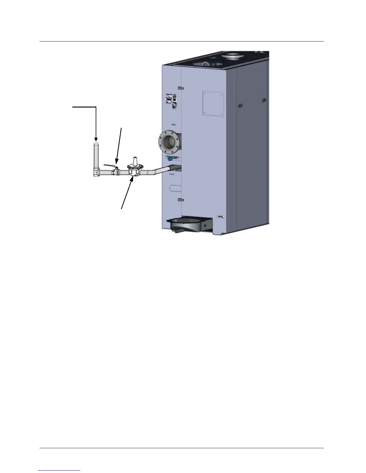
Figure 2-8: Manual Gas Shut-Off Valve Location
2.9 AC ELECTRICAL POWER WIRING
The AERCO Benchmark Electrical Power Wiring Guide, GF-2060, must be consulted prior to
connecting any AC power wiring to the unit. External AC power connections are made to the unit
inside the Power Box on the front of the unit. Remove the unit’s front panel to access the Power
Box, which is mounted in the upper right corner of the unit as shown in Figure 2-9. Loosen the
four Power Box cover screws and remove the cover to access the AC terminal block
connections, and other internal components shown in Figure 2-10.
GAS
SUPPLY
GAS SHUT-
OFF VALVE
REGULATOR