Benchmark 6000 Boiler Installation, Operation & Maintenance Manual
CHAPTER 10 – BOILER SEQUENCING TECHNOLOGY
OMM-0086_0D AERCO International, Inc. • 100 Oritani Dr. • Blauvelt, NY 10913 Page 143 of 210
GF-133 Ph.: 800-526-0288 03/20/14
10.3.5 Option 5 - Remote Setpoint with DIRECT WIRED Header Sensor AND 4-
20ma Setpoint Drive
NOTE: Both Header Sensor AND 4-20ma Direct Drive must be wired. See the C-More Controller User
Manual, OMM-0032, GF-112 and ProtoNode User Manual, OMM-0080, GF-129 for more information.
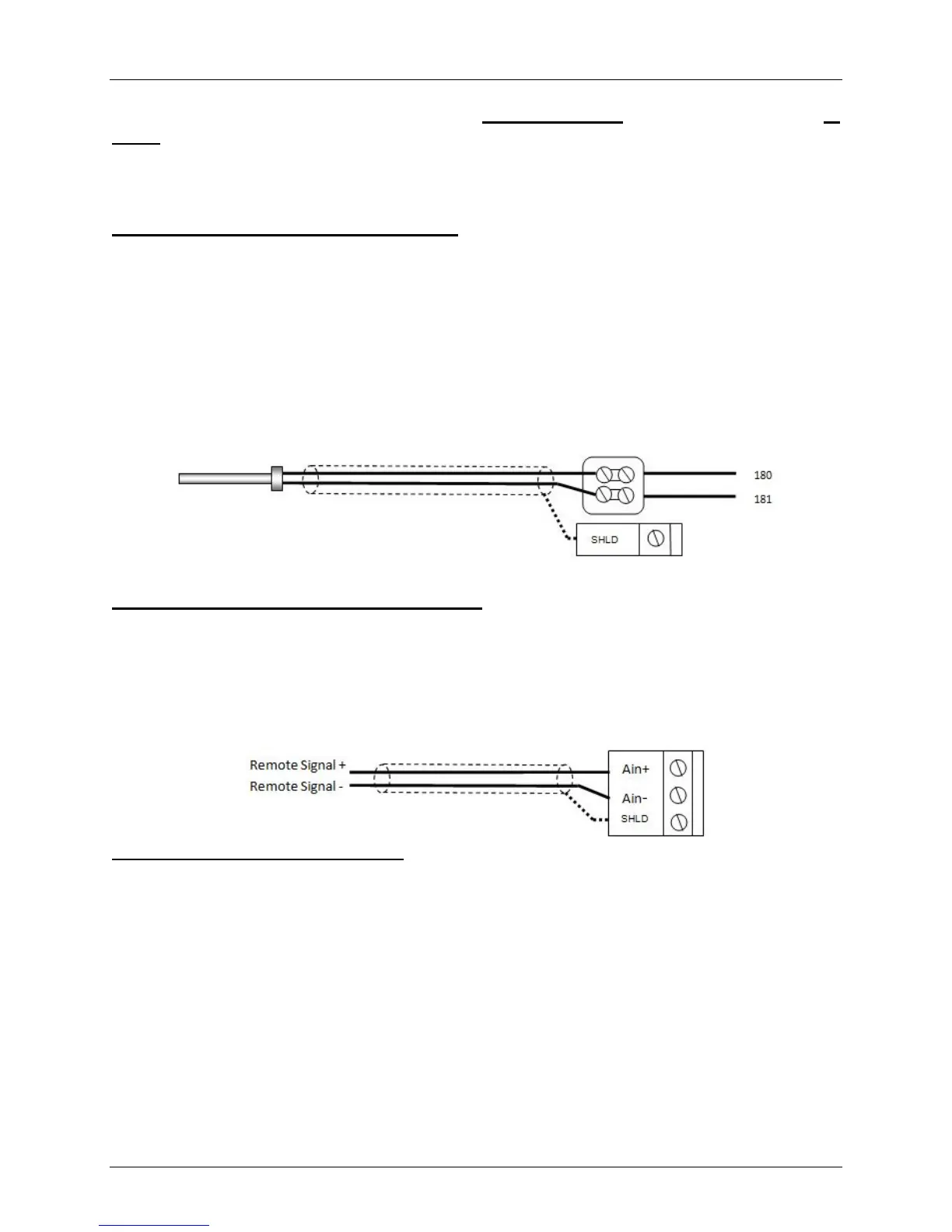
Step 1: Direct Wired Header Sensor Wiring
1. On the MASTER Unit, Connect the Header Temperature Sensor (AERCO PN 61040) to the Feed
Forward (FFWD) terminals on the P-1 Harness Via the terminal block labeled “Header Temp sensor”
in the I/O Box.
NOTES:
• The header sensor must be installed between 2 and 10 feet downstream of the LAST boiler
in the plant’s supply water header.
• Shielded pair 18 - 22 AWG cable is recommended for header sensor wiring.
• There is no polarity to be observed.
• The ground for the shield is at the “SHLD” terminal in the I/O the Box.
• The sensor end of the shield must be left free and ungrounded.
Step 2: Direct Wired 0-20ma or 4-20ma Wiring
1. Connect the 4-20ma or 0-20ma terminals from the Direct Drive source to the Ain+ and Ain- terminals
on the Master Unit’s I/O Box.
NOTE:
• Shielded pair 18 - 22 AWG cable is recommended for this connection. Polarity must be
observed.
• The ground for the shield is at the driver signal source.
Step 3: Configure ALL C-More Units
On ALL Boilers:
1. Go to the Configuration Menu and set the BST Menu item to Enabled.
2. Go to the BST Menu and set the BST Mode item to BST Slave (for now) .
On MASTER only:
3. Go to the BST Setpoint item and enter the Failsafe Setpoint.
4. Go to the BST Setup Menu item and set to Enabled.
5. Go to the BST Setpoint Mode item and select Remote Setpoint.
6. Go to the Head Temp Source item and select FFWD Temp.
7. Go to the BST Remote Signal and select either 4-20ma or 0-20ma.
When ALL C-More units have been configured:
8. Go to the BST Menu of the desired Master unit and set the BST Mode item to BST MASTER.
Temp Sensor PN 61040 Header Temp Sensor I/O Box