Benchmark 6000 Boiler Installation, Operation & Maintenance Manual
CHAPTER 2 – INSTALLATION
OMM-0086_0D AERCO International, Inc. • 100 Oritani Dr. • Blauvelt, NY 10913 Page 19 of 210
GF-133 Ph.: 800-526-0288 03/20/14
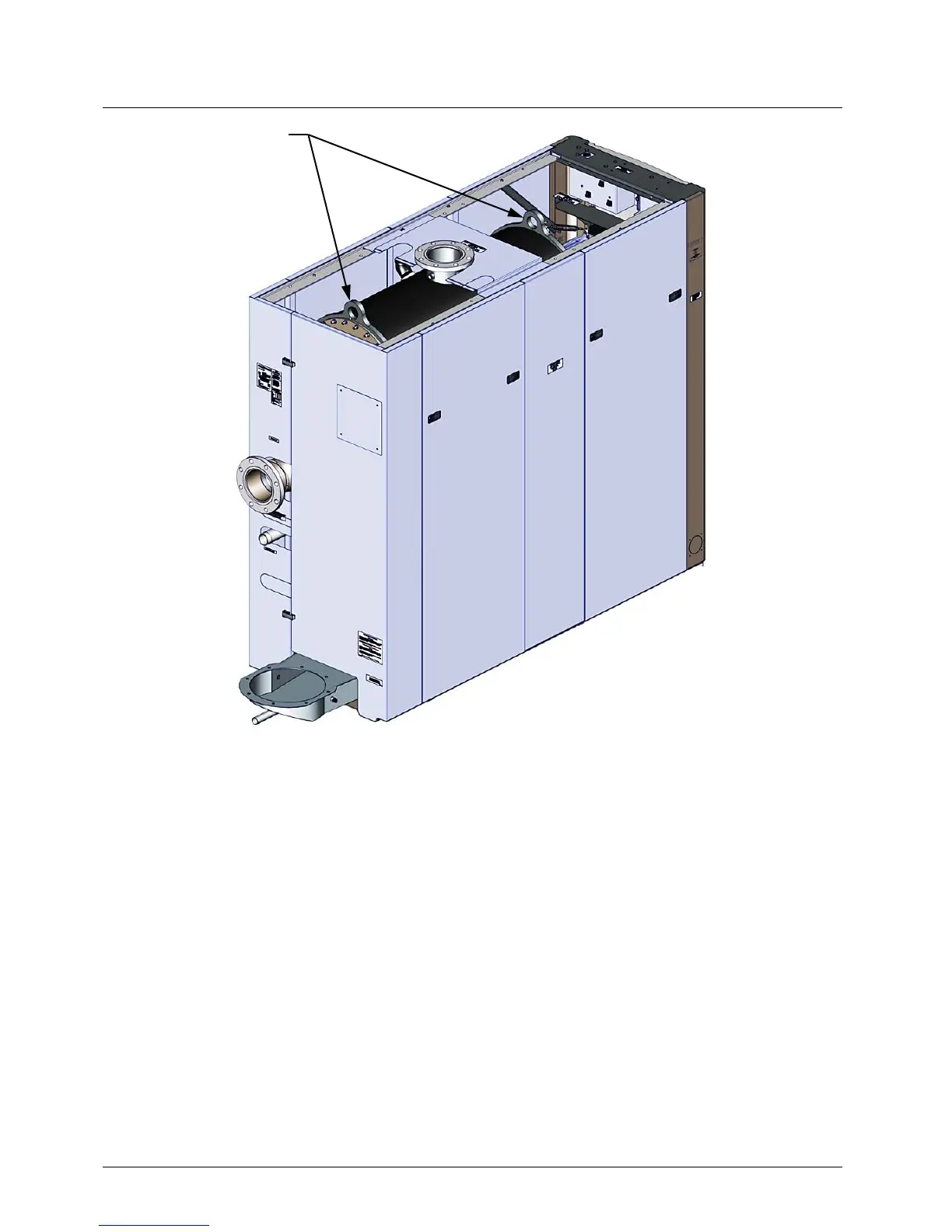
Figure 2-3: Boiler Lifting Provisions
If anchoring the unit, refer to the dimensional drawings in Appendix F for anchor locations.
In multiple unit installations, it is important to plan the position of each unit in advance. Sufficient
space for piping connections and future service/maintenance requirements must also be taken
into consideration. All piping must include ample provisions for expansion.
If installing a Combination Control Panel (CCP) system, it is important to identify the Combination
Mode Boilers in advance and place them in the proper physical location. Refer to Chapter 5 for
information on Combination Mode Boilers.
2.5 SUPPLY AND RETURN PIPING
The Benchmark Boiler utilizes 6” flanged fittings for the water system supply and return piping
connections. The physical location of the supply and return piping connections are shown in
Figure 2-4. Refer to Appendix F, Drawing AP-A-901 for additional dimensional data.
Remove the two top panels
to access the lifting tabs.