Benchmark 6000 Boiler Installation, Operation & Maintenance Manual
CHAPTER 10 – BOILER SEQUENCING TECHNOLOGY
Page 142 of 210 AERCO International, Inc. • 100 Oritani Dr. • Blauvelt, NY 10913 OMM-0086_0D
03/20/14 Ph.: 800-526-0288 GF-133
Option 4 – Continued
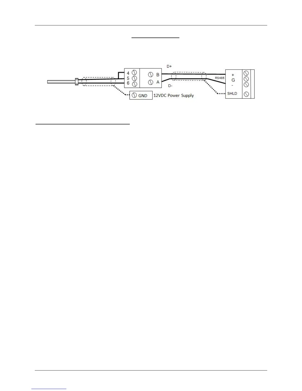
• There is no polarity to be observed. The ground for the shield is at the power supply
ground. The sensor end of the shield must be left free and ungrounded.
Step 3 - Configure ALL C-More Units
On ALL Boilers:
1. Go to the Configuration Menu and set the BST Menu item to Enabled.
2. Go to the BST Menu and set the BST Mode item to BST Slave (for now).
On MASTER only:
3. Go to the BST Setpoint item and enter the Failsafe Setpoint.
4. Go to the BST Setup Menu item and set to Enabled.
5. Go to the BST Setpoint Mode item and select Outdoor Reset.
6. Go to the Head Temp Source item and select Network.
7. Go to the Header Temp Addr item and enter the Modbus Address (240).
8. Go to the Header Temp Point item and enter the Modbus Point (14).
9. Go to the BST Outdoor Sens item and select Enabled.
10. Go to the Outdoor Temp Source item and select Network.
11. Go to the Outdoor Temp Addr item and enter the Modbus Address (240).
12. Go to the Outdoor Temp Point item and enter the Modbus Point (15).
When ALL C-More units have been configured:
13. Go to the BST Menu of the desired Master unit and set the BST Mode item to BST MASTER.
Temp Sensor PN 61043 Modbus Transmitter I/O Box