Benchmark 6000 Boiler Installation, Operation & Maintenance Manual
CHAPTER 2 – INSTALLATION
Page 26 of 210 AERCO International, Inc. • 100 Oritani Dr. • Blauvelt, NY 10913 OMM-0086_0D
03/20/14 Ph.: 800-526-0288 GF-133
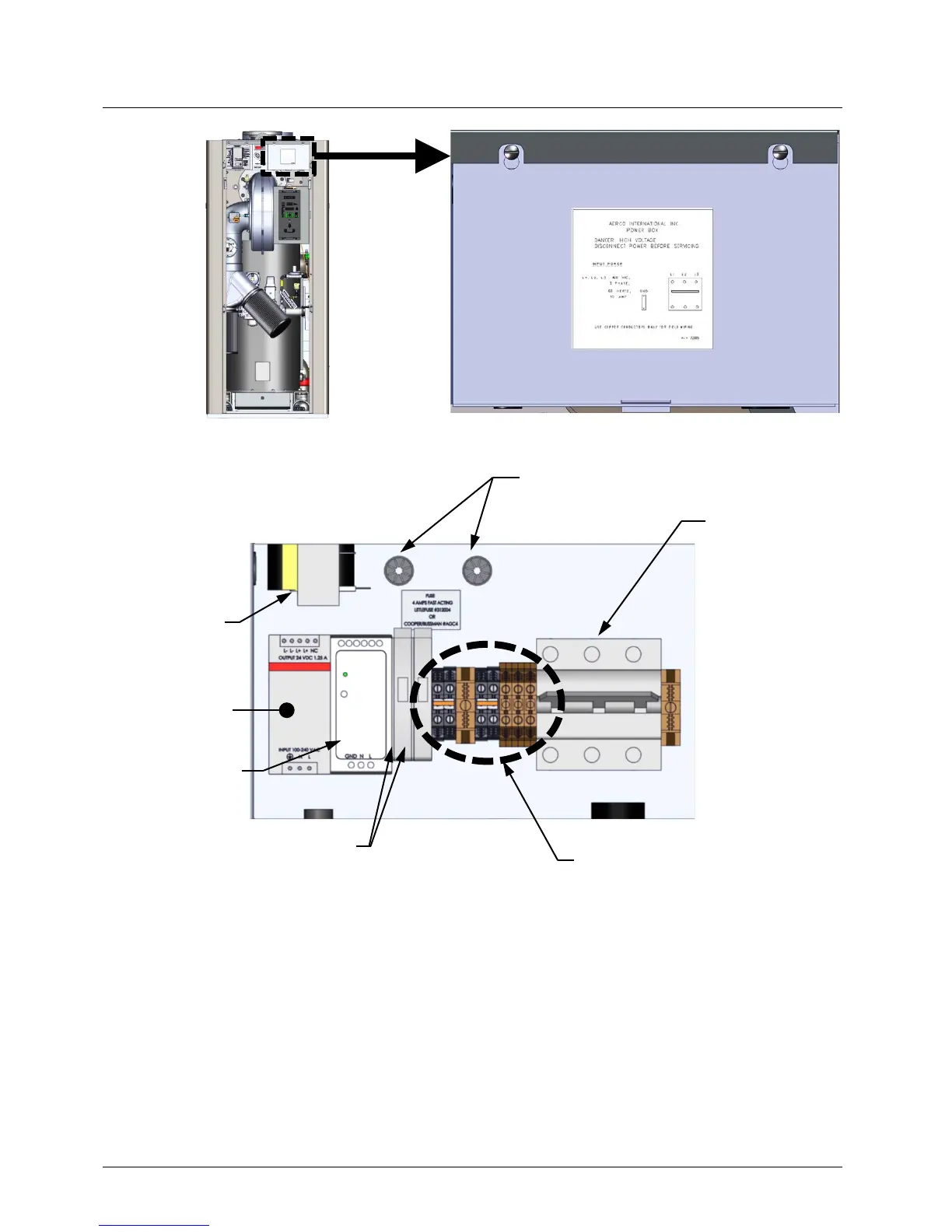
Figure 2-9: Power Box With Closed Cover
Figure 2-10: Power Box Internal Components
With the exception of the transformer shown in Figure 2-10, all of the components in the Power
Box are mounted on a DIN rail.
NOTE
All electrical conduit and hardware must be installed so that it does
not interfere with the removal of any unit covers, inhibit
service/maintenance, or prevent access between the unit and walls
or another unit.
located in the
unit’s upper-
right corner.
WIRE CONDUITS
POWER
BREAKER
TRANSFORMER
12V POWER
SUPPLY
24V POWER
SUPPLY