English
25
IFCLIJ 1107 - 4528500_04
ATTENTION: before carrying out any
intervention, make sure that the elec-
tric power supply has been disconnec-
ted.
ATTENTION: before carrying out any
work, wear the appropriate individual
protection devices.
ATTENTION: The appliance must be
installed in compliance with national
regulations on this subject.
ATTENTION: the electric connections,
the installation of the fan coils and
their accessories must only be perfor-
med by subjects with the technical-
professional requisites for enabling
and installation, transformation, exten-
sion and maintenance of the systems
and able to check the same for safety
and functionality purposes (in this
manual they will be indicated by the
generic term "staff with specific tech-
nical skill").
In particular, for the electric connec-
tions, checks relative to the following
are requested:
- Measurement of the electric plant iso-
lation resistance.
- Continuity test of the protection wires.
ATTENTION: Install a device, master
switch or electric plug that allows to
completely interrupt the appliance’s
electric power supply.
Here find the essential indications for
correct installation of the appliance.
The completion of all operations, accor-
ding to specific requirements, is left to
the experience of the installer.
The water, condensate drainage and
electrical circuit ducts must be provi-
ded for.
The fan coil must be installed in a
position such to easily allow routine
maintenance (cleaning the filter) and
extraordinary maintenance, as well as
access to the air vent valve on the side
of the frame (connections side).
Do not install the unit in rooms where
inflammable gases or acid or alkaline
substances are present that can perma-
nently damage the copper-aluminium
heat exchangers or internal plastic
components.
Do not install the unit in workshops
or kitchens, where oil vapours mixed
with the treated can deposit on the
heat exchanger coils, reducing their
performance, or on the internal parts
of the unit, thus damaging the plastic
components.
The fan coil must be installed in a posi-
tion such that the air can be distributed
throughout the entire room, that there
are no obstacles (curtains or objects) to
the passage of air from the intake grids.
Choose a position in the centre of the
room if possible; the regulation of the
air output allows the air to be distribu-
ted optimally in the room. Generally
the best position of the fins is that that
allows the launch of the air adhering to
the ceiling for the coined effect, during
cold functioning. The side section of
the deflectors (Module 600)shows the
opening positions for proper warm fun-
ctioning (opening 20°) and cold fun-
ctioning (opening 10°) of the machine.
For the Module 840 units, it is recom-
mended to completely open the deflec-
tor in heating mode. In cooling mode,
rotate the deflector to half way.
Depending on the user's requirements, it
is possible to position the louvered fins
in the intermediate of complete closure
positions. Thanks to the special shapes
of the louvered fins the machine can
also function with the deflectors com-
pletely closed.
Do not install at height of above three
metres.
The FCL unit is set for connection with
fresh air ducts and for the flow of the
treated air in an adjacent room.
INSTALLATION
SA
SA
SA
SA
SW4
SW4
SW4
SA
SA
VHL
VHL
VHL
VHL1
VHL20
VHL
RXLE
RXLE
SW4
VHL1
VHL2
SA
SA
SW4
SW4
SW4
SA
SA
VHL
VHL
VHL
VHL2
VHL22
VHL
RXLE
RXLE
SW4
VHL1
VHL2
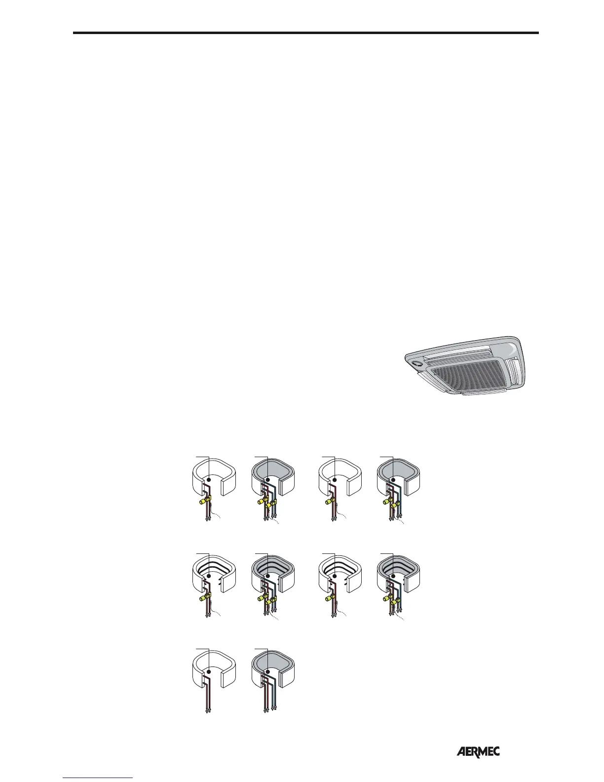
Key:
SA Room temperature probe
SW Water temperatur probe
RXLE Electric heater (for Module 600 only)
VHL Solenoid valve ( Heating/Cooling)
VHL1 / VHL20 Hot Valve (3-way)
VHL2 / VHL22 Hot Valve (2-way)
2-pipe systemi 4-pipe system
2-pipe system with resistance
(Only for models and confi gu-
rations that envision heating
with resistance)
4-pipe system with resistance
(Only for models and confi gu-
rations that envision heating
with resistance)
SYSTEM EXAMPLES