44
This section is reserved to the After-sales Service Centres only.
The board is found inside the unit and requires disassembly.
DANGER! Only qualified maintenance personnel can access it.
On the Inverter board there are 2 LED (Alarm/Power) indicating
the operating status of the unit.
The following table indicates how to decode the messages.
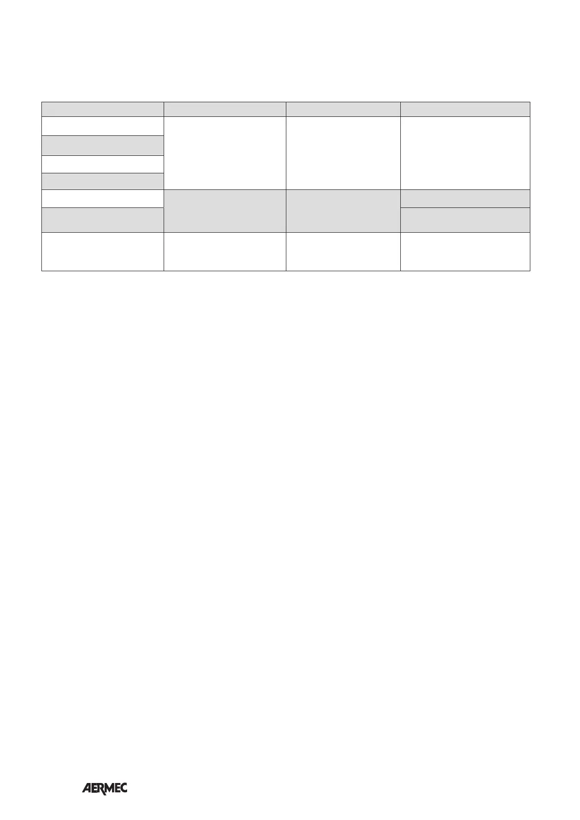
ALARM CODE
ALARM TYPE INDICATIONS ANOMALY NOTES
High temperature
Flashing ALARM LED
3sec ON 0.5sec OFF
After 1.5 min the LED is
permanently on
Motor off
Auto-Restart alarm
If the conditions persist after
1.5 min, the alarm becomes
permanent, the Alarm LED remains
on, the system turns off.
Over-voltage
Under-voltage
Over-current
Overload
Flashing ALARM LED
0.5sec ON 0.5sec OFF
Speed reduction
Power limitation
Safety control Temperature limitation
STOP Alarm LED permanently ON Motor off
To reset the alarms:
Set 0V ON INPUT
(disconnect voltage and switch on
again)