27
INSTALLATION
WARNING: before carrying out any
work, make sure the power supply is dis-
connected.
WARNING: before carrying out any work,
put the proper individual protection
devices on.
WARNING: the device must be installed in
compliance with the national plant engi-
neering rules.
WARNING: the electrical connections, the
installation of the fan coils and relevant
accessories should be performed by a
technician who has the necessary tech-
nical and professional expertise to install,
modify, extend and maintain systems,
and who is able to check the systems
for the purposes of safety and correct
operation (in this manual they will be
indicated with the general term "persons
with specific technical skills").
In the specific case of electrical wirings,
the following must be checked:
- measurement of the electrical system
insulation strength
- continuity test of the protection wires
WARNING: install a device, main switch, or
electric plug so you can fully disconnect
the device from the power supply.
The essential indications to carry out a
proper installation are given below.
The final touches to all the operations are,
however, left to the experience of the
installation engineer in accordance with
the specific needs.
The water, condensate discharge and elec-
trical circuit ducts must be provided for.
The fan coil should be installed in such a
way as to facilitate routine (filter clean-
ing) and special maintenance opera-
tions, as well as access to the air drain
valve on the side of the unit frame (con-
nections side).
Do not install units in rooms where there
are inflammable gases or acid or alka-
line substances that could irreparably
damage the aluminium-copper heat
exchanger or internal plastic parts.
Do not install the unit in workshops or
kitchens, where oil vapours mixed with
the treated air can be deposited on the
exchange coils, reducing their effective-
ness, or on the internal parts of the unit,
damaging the plastic components.
The fan coil must be installed in such a
position that the air can be distributed
throughout the room and so that there
are no obstacles (curtains or objects) to
the passage of the air from the suction
grilles.
Choose a position at the centre of the
room whenever possible; adjusting the
air output allows air to be distributed
optimally within the room. Generally the
best position of the fins is that which
allows the launch of the air adhering to
the ceiling for the coined effect, during
cold functioning.
On the side of the deflectors there is an
indication of the opening positions for
correct operation:
- Module 600 hot opening 20°
- Module 600 cold opening 10°
- Module 840 hot opening 25°; 100%
- Module 840 cold opening 50°
Depending on the user's needs, the fins
can be adjusted to the intermediate
positions, or completely closed.
Thanks to the special shapes of the fins,
the machine can also function with the
deflectors completely closed.
Do not install at a height above three
metres.
The FCLI unit is prepared for connections
with channelling for the fresh air and for
the delivery of treated air to an adjacent
room.
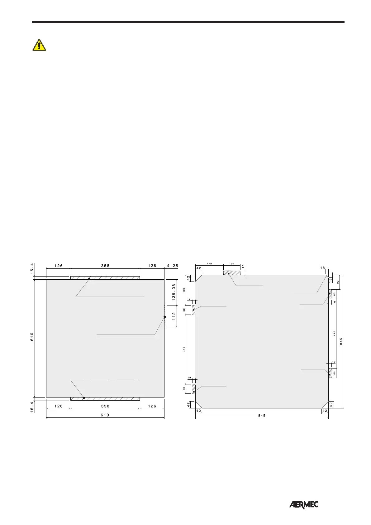
RECOMMENDED INSTALLATION TEMPLATE
Max. dimensions of water connections
Max. dimensions of installation bracket
Max. dimensions of installation bracket
Module "600" Module "840"
Max. dimensions of
installation bracket
Max. dimensions of
installation bracket
Max. dimensions of
installation bracket
Max. dimensions of
installation bracket
Condensate drain
side
Max. dimensions of
water connections