22 22.05 4037360_01
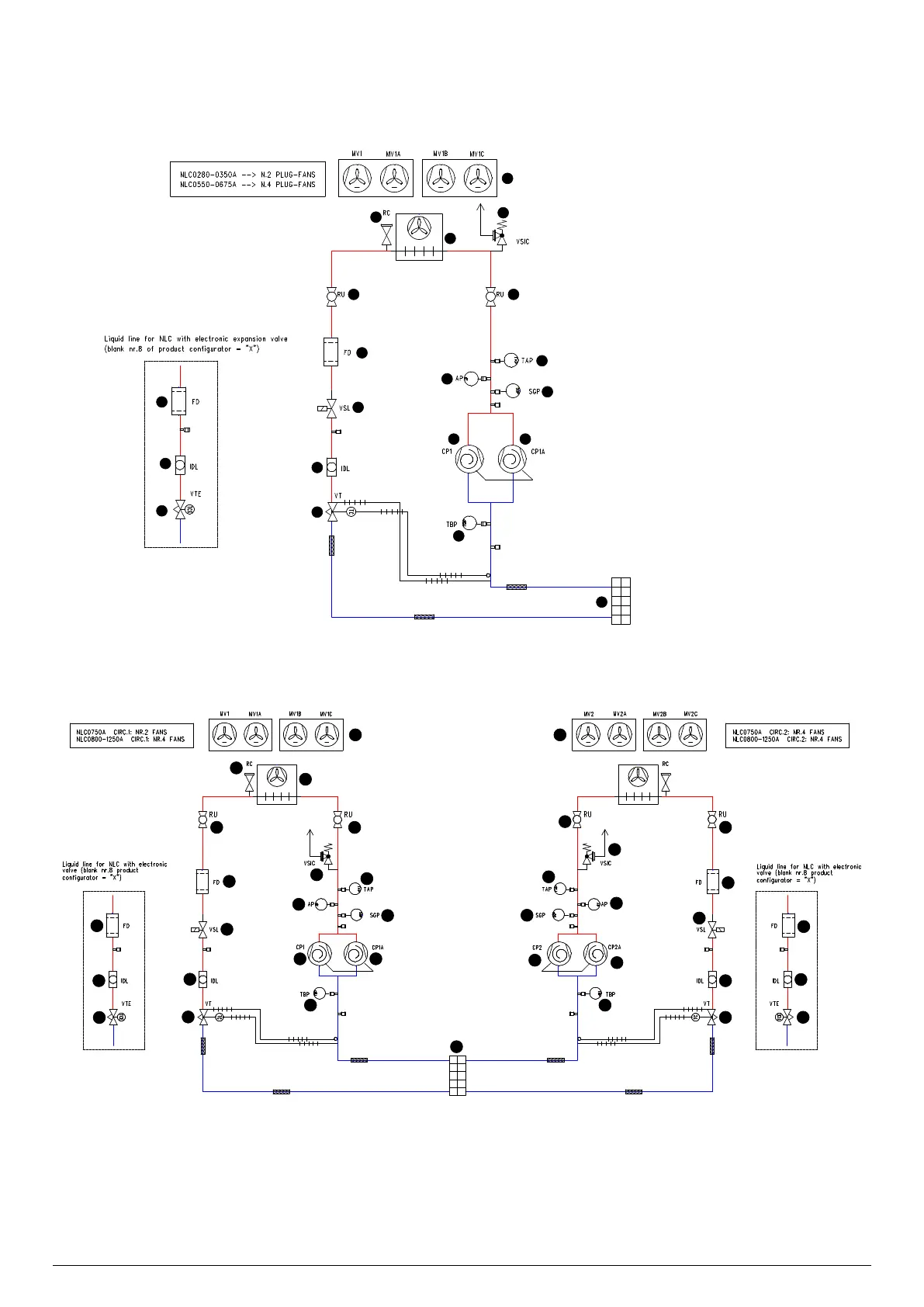
5 REFRIGERANT CIRCUIT
NLC 02800675 A
1 Fan Plug-fan
2 Charging connection
3 Finned coil
4 Pressure relief valve
5 Isolation valve
6 High pressure transducer
7 High pressure switch
8 Discharge temperature sensor
9 Compressor
10 Low pressure transducer
11 Plate heat exchanger
12 Mechanic thermostatic valve
13 Sight glass
14 Solenoid valve
15 Filter drier
16 Electronic thermostatic ex-
pansion valve
2
3
4
55
6
7
8
99
10
11
12
13
13
14
15
15
16
NLC 07501250 A
1 Fan Plug-fan
2 Charging connection
3 Finned coil
4 Isolation valve
5 Pressure relief valve
6 High pressure transducer
7 High pressure switch
8 Discharge temperature sensor
9 Compressor
10 Low pressure transducer
11 Plate heat exchanger
12 Mechanic thermostatic valve
13 Sight glass
14 Solenoid valve
15 Filter drier
16 Electronic thermostatic expansion valve
2
3
4
4
4
4
5
5
6
6
7
7
8
8
9
9
9
9
10 10
12
16
13
13
14
15
15
11
12
13
13
14
15
15
16