7
CARATTERISTICHE
•
FEATURES
DESCRIZIONE DEI COMPONENTI
1 SCAMBIATORE LATO ARIA
È realizzato con tubi di rame ed alette in alluminio bloccate
mediante espansione meccanica dei tubi. È del tipo ad alta
efficienza; alette intagliate per le versioni solo freddo, tubo
rigato ed alette corrugate per le versioni a pompa di calore.
2 VALVOLA INVERSIONE CICLO (Pompa di calore)
Inverte il flusso di refrigerante al variare del funzionamento
estivo / invernale.
3 VALVOLA TERMOSTATICA
La valvola con equalizzatore esterno, posto all’uscita
dell’evaporatore, modula l’afflusso di gas all’evaporatore in
funzione del carico termico in modo da assicurare un suffi-
ciente grado di surriscaldamento al gas di aspirazione.
4 VALVOLA SOLENOIDE DI BY-PASS (Pompa di calore)
Esclude la valvola termostatica durante il ciclo di sbrinamen-
to.
5 COMPRESSORE
Compressori ermetici di tipo alternativo o scroll a seconda
dei modelli, tutti i compressori sono dotati di cuffia fono-
isolante. Il vano compressori è isolato acusticamente.
6 FILTRO DEIDRATATORE
Di tipo meccanico realizzato in ceramica e materiale igro-
scopico, in grado di trattenere le impurità e le eventuali
tracce di umidità presenti nel circuito frigorifero.
7 VALVOLA UNIDIREZIONALE (Pompa di calore)
Consente il passaggio del liquido refrigerante in una sola
direzione.
8 PRESSOSTATO DI ALTA
A taratura fissa, posto sul lato ad alta pressione del circuito
frigorifero, arresta il funzionamento del compressore in caso
di pressioni anomale di lavoro.
9 SPIA DEL LIQUIDO
Serve per verificare la carica di gas frigorigeno e l’eventuale
presenza di umidità nel circuito frigorifero.
10 PRESSOSTATO DIFFERENZIALE LATO ACQUA
È montato tra l’entrata e l’uscita dello scambiatore e, in caso
di portata d’acqua troppo bassa, ferma il compressore.
11 SCAMBIATORE LATO ACQUA
Del tipo a piastre (AISI 316), è isolato esternamente con
materiale a celle chiuse per ridurre le dispersioni termiche.
12 TASTIERA DI COMANDO
Consente il controllo completo dell’apparecchio. Per una più
dettagliata descrizione si faccia riferimento al manuale d’uso.
13 QUADRO ELETTRICO
Contiene la sezione di potenza e la gestione dei controlli e
delle sicurezze. È conforme alle norme EN 60335-1, EN
60335-2-40.
14 STRUTTURA PORTANTE
Realizzata in lamiera di acciaio zincata a caldo, di adegua-
to spessore, è verniciata con polveri poliuretaniche per
garantire la resistenza agli agenti atmosferici.
15 GRUPPO VENTILANTE
Di tipo elicoidale, è equipaggiato di ventole bilanciate statica-
mente e dinamicamente, che sono direttamente calettate
sull’albero del motore. Gli elettroventilatori sono protetti elettri-
camente con interuttori magnetotermici e meccanicamente con
griglie metalliche fissate sulla parte superiore della carpenteria.
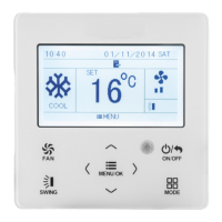
16 PANNELLO DI COMANDO A DISTANZA
Consente di eseguire a distanza le seguenti operazioni:
– accensione e spegnimento dell’unità ON / OFF (visualiz-
zazione tramite spia gialla);
– selezione del tipo di funzionamento raffreddamento /
COMPONENT DESCRIPTION
1 AIR SIDE EXCHANGER
Made of aluminium fins mechanically bonded to copper
pipes. High efficiency coil; slotted fins for the cooling only
versions, inner grooved pipes and corrugated fins for the
heat pump versions.
2 4-WAY VALVE (Heat pump)
Inverts the flow of refrigerant when the summer / winter
operation mode is changed.
3 THERMOSTATIC VALVE
The valve with external equaliser is fitted on the outlet of the
evaporator and modulates the flux of gas to the evaporator
according to the thermal load, to ensure an adequate level
of overheating of the suction gas.
4 BY-PASS SOLENOID VALVE (Heat pump)
This overrides the thermostatic valve during the defrost
cycle.
5 COMPRESSOR
Hermetic compressors either reciprocating or scroll depen-
ding on the models, all the compressors are fitted with an
acoustic jacket. The compressor housing is soundproofed.
6 FILTER DRYER
A mechanical filter in ceramic and hygroscopic material,
capable of retaining the impurities and any traces of humi-
dity present in the refrigerant circuit.
7 NON RETURN VALVE (Heat pump)
To permit refrigerant liquid flow only one direction.
8 HIGH PRESSURE SWITCH
With a fixed calibration, mounted on the high pressure side
of the refrigerant circuit, it blocks operation of the compres-
sor in the event of abnormal working pressures.
9 SIGHT GLASS
To check the presence of refrigerant and possible traces of
moisture in the circuit.
10 WATER SIDE DIFFERENTIAL PRESSURE SWITCH
It is mounted across the inlet and outlet of the exchanger and, in
the event that the water flow is too low, it blocks the compressor.
11 WATER SIDE EXCHANGER
A plate exchanger (AISI 316) externally lined with closed
cell insulation to reduce heat dispersion.
12 CONTROL KEYBOARD
It permits a complete control of the unit. For a more detailed
description consult the user's manual.
13 SWITCHBOARD
It contains the power section and the management of the
controls and safeties. It has conform to EN 60335-1, EN
60335-2-40.
14 CHANNEL FRAME
Made of hot galvanised steel sheet, of substantial thickness,
it is painted with polyurethanic powder to guarantee a long-
term weather resistance.
15 FAN GROUP
Propeller fans, fitted with statically and dynamically balan-
ced fans directly keyed to the motor shaft. Electric fans are
electrically protected by thermal-magnetic circuit breakers,
and mechanically protected by metal grilles secured to the
upper section of the unit housing.
16 REMOTE CONTROL PANEL
It allows the following operations to be remote controlled:
– ON / OFF of the unit (signaled by a yellow light);
– Selection of summer / winter operating modes (signaled
by green / red lights);
 Loading...