EasyManua.ls Logo

AERMEC WRC1 User Manual

AERMEC WRC1
192 pages
Go to English
To Next Page IconTo Next Page
Page #1 background imageLoading...
Page #1 background image
IT
5389636_01
MANUALE USO
WRC1
EN FR DE ES

Table of Contents

Question and Answer IconNeed help?

Do you have a question about the AERMEC WRC1 and is the answer not in the manual?

AERMEC WRC1 Specifications

General IconGeneral
BrandAERMEC
ModelWRC1
CategoryControl Panel
LanguageEnglish

Summary

Wired panel WRC1

User interface (display)

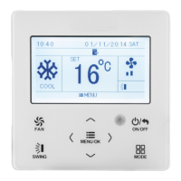
Describes the LCD display and icons for functions.

Wired panel LCD Icons

Function Icons Overview

Details the meaning of icons on the LCD display.

User interface (keys)

Wired Panel Button Functions

Explains the function of each button on the wired panel.

Installing the wired panel

Wired Panel Dimensions

Provides physical dimensions for the wired panel.

Electrical Box Dimensions

Provides physical dimensions for the electrical box.

Serial connection types

Single Wired Panel Connection

Describes a single wired panel managing one or more units.

Dual Wired Panel Connection

Describes two wired panels managing units (master/slave).

Serial Connection Examples

Panel to Unit Serial Connection

Illustrates serial connection between panel and indoor units.

Wired panel installation procedure

Opening the Wired Panel

Details how to open the wired panel for installation.

Installing the Metal Electrical Box

Describes the installation of the metal electrical box.

Gate Control Function

Wired Panel Cable Connections

Serial Connection Cable Specifications

Specifies requirements for serial communication cables.

Incoming Signal Type Connection

Explains managing different signal types (AC/DC).

Final Wired Panel Installation Steps

Securing the Wired Panel Body

Details how to secure the panel body to the box.

Installation Notes and Warnings

Advises on suitable installation locations and restrictions.

Functions Available via Wired Panel

Switching Indoor Unit ON/OFF

How to turn the unit on and off using the panel.

Modifying Operating Mode

Mode Selection Overview

Explains how to change the unit's operating mode.

AUTO Mode Operating Logic

Explains the logic behind the automatic operating mode.

Modifying Operating Temperature

Modifying Fan Speed

Programmed ON/OFF Timer (Countdown Mode)

Setting Countdown Timer

How to set programmed ON/OFF operations using countdown.

Setting System Time (Clock Mode)

Clock Mode Time Adjustment

Procedure to set the system time in clock mode.

Programmed ON/OFF Timer (Clock Mode)

Time Band Management

Setting ON and OFF times for a specific band.

Programmed Switch ON Only

Setting only the ON time for the unit.

Programmed Switch OFF Only

Setting only the OFF time for the unit.

Set Delivery Fin SWING

SWING Mode Operation

How to cycle through SWING function statuses.

Set QUIET Function

QUIET and AUTO QUIET Modes

Explains QUIET and AUTO QUIET fan speed management.

Setting Night-Time Comfort Function

SLEEP Function Activation

How to activate the night-time comfort function.

Set DISPLAY Function

Indoor Unit Display Illumination

How to activate or deactivate the indoor unit display.

Set ENERGY SAVING Function

Energy Saving Mode Settings

How to set min/max limits for energy saving mode.

Set FILTER CLEANING Alarm

Filter Cleaning Alert Configuration

Sets the interval for filter cleaning alerts.

Set X-FAN Function

X-FAN Function Activation

Activates X-FAN to dry the coil after shutdown.

Set ANTIFREEZE Function

ANTIFREEZE Function Activation

Activates ANTIFREEZE to prevent freezing in heat mode.

Set Key LOCK on Wired Panel

Panel Button Lock Activation

Locks or unlocks the wired panel buttons.

Display Indoor Unit OPERATING PARAMETERS

Parameter Display Procedure

How to access and view operating parameters.

List of Operating Parameters (Read-Only)

System Identification and Configuration Parameters

Project numbers, unit counts, addresses, priority, group size.

Error Monitoring and Temperature Display

System error monitor, room and external temperatures.

Maintenance and Alerts

Filter cleaning alarm settings.

Display All Project Numbers

Simultaneous Project Number Display

Displays all project numbers simultaneously.

Activate OPERATING PARAMETER Modification Menu

Set System MASTER Unit (P10)

Designates an indoor unit as the system master.

Enable Infra-Red Remote Controls (P11)

Activates or deactivates infra-red remote control functions.

Set Wired Panel Address (P13)

Assigns an address to the wired panel.

Operating Parameter Settings

Group and Measurement Settings (P14, P16)

Set number of units in group and unit of measure.

Clock and Timer Settings (P33, P34)

Configure clock type and repetition of time settings.

Cooling and Heating Setpoints (P37)

Define cool setpoint for AUTO mode.

More Operating Parameter Settings

Heating Setpoint for AUTO Mode (P38)

Defines the heating setpoint for AUTO mode.

Unit Priority and Filter Alarm (P43, P46)

Set indoor unit priority and enable filter cleaning alarm.

Delivery Fin Opening Setting (P49)

Sets the default delivery fin position on startup.

Activate ADVANCED OPERATING PARAMETER Modification Menu

Setting Temperature Sensor Source (P20)

Selects the temperature sensor source for indoor unit operation.

Setting Continuous Ventilation to Hot (P56)

Configures continuous ventilation for heating mode.

Display Operating Errors or System Messages

Alarm Code Overview

Lists alarm codes, unit types, and causes.

Operating Error Codes (Part 2)

Error Code Explanations (F7-FU)

Continues listing error codes and their meanings.

Operating Error Codes (Part 3)

Error Code Explanations (b4-P3)

Continues listing error codes and their meanings.

Operating Error Codes (Part 4)

Error Code Explanations (LH-Ad)

Continues listing error codes and their meanings.

Operating Error Codes (Part 5)

Error Code Explanations (U4-Cb)

Continues listing error codes and their meanings.

Related product manuals