47
EN
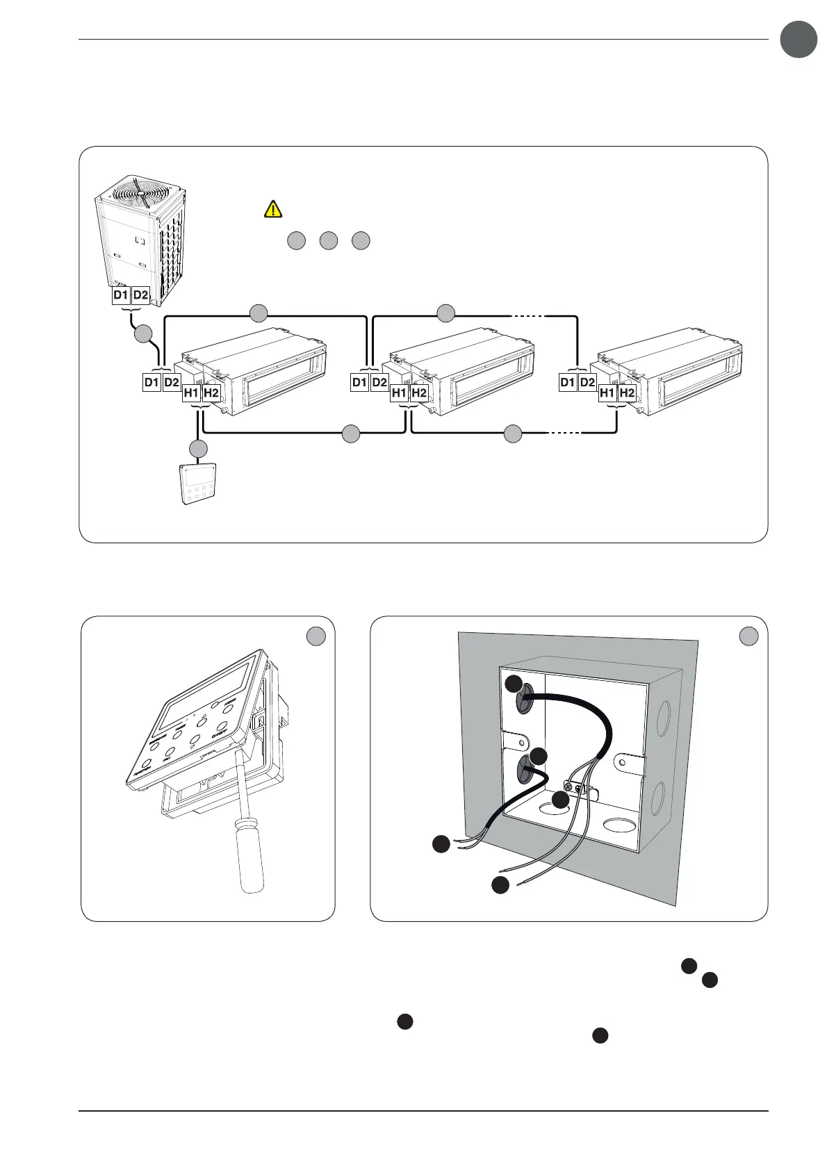
Outdoor unit
Indoor unit (A) Indoor unit (B) Indoor unit (n)
Wired panel
1
3
2
5
4 6
WARNING:
2
+
4
+
6
≤ 250m
The second serial connection possibility envisages only one
panel (reminder: each individual unit of group of units can be
managed by a single panel or by two panels connected to
the same Indoor unit in MASTER/SLAVE mode, as indicated in
the previous page) for the overall group of units (a group may
comprise max. 16 units); this solution allows unique settings
for the timer, setpoint and ventilation speed for all the Indoor
units in the group;
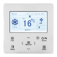
The fi rst operation needed to install the wired
panel is to open it using a fl at screwdriver by
pressing in the specifi c slot on the base of the
panel.
1
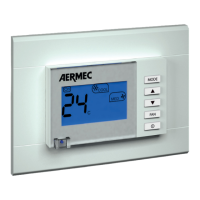
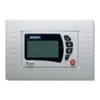
Wired panel installation procedure:
The metal electrical box supplied as standard must be installed on the
wall; after preparing the wall in a suitable manner, insert the cables (re-
member to use the rubber fairlead supplied as standard
A
):
• A two-pole cable for serial connection with the indoor unit (
C
);
• A three-pole cable (for more information about connection cable fea-
tures, refer to the specifi c section) to connect the external contact if pres-
ent (
D
); THE ELECTRICAL BOX MUST BE CONNECTED TO EARTH/
GROUND USING THE SPECIFIC TOOL (
B
) AND SCREW SUPPLIED AS
STANDARD
2
A
A
B
C
D