Do you have a question about the AERMEC FMT21 and is the answer not in the manual?
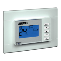
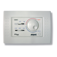
Allows selection of heating, cooling, automatic, or fan-only operation.
Manages water temperature for heating/cooling, preventing ventilation if water temp is unsuitable.
Manual or automatic fan speed selection, including continuous operation.
Accessory for detecting water or air temperature, disabling internal sensor.
Fan runs continuously, even after set temp is reached, at minimum speed if auto.
Fan switches off automatically when the set temperature is reached.
Shows working settings and temperature.
Allows selection of desired operational mode.
Buttons for modifying temperature settings.
Sets fan speed (low, average, maximum, auto).
Switches fan coil on/off and converts temp scale (°C/°F).
Displays continuous or thermostat-controlled ventilation status.
Shows current fan speed setting.
Indicates water temperature issues or sensor alarms.
Controls the power state of the fan coil unit.
Cycles through HEAT, COOL, AUTOMATIC, and FAN modes.
Details how to set temperature and fan speed for heating.
Details how to set temperature and fan speed for cooling.
Explains automatic mode and setting temperature/fan speed.
Operates fan coil without water circulation, fixed to max speed in auto.
Manual selection of low, med, high fan speeds or automatic control.
Fan runs continuously, even after target temperature is met.
Fan automatically switches off once the target temperature is reached.
Ensures power disconnection and professional installation for safety.
Flush mounting in a 3-module box, avoid direct sun/draughts.
Connects SWA probes for water or air temperature sensing.
Uses SWA probe for water temp, active only in Auto mode, 2-pipe systems.
Uses SWA probe for room air temp, disabling internal sensor.
Explains symbols and component abbreviations used in diagrams.
Diagram for a 2-tube fan coil system with valve.
Details optional components and on-site wiring connections.
Diagram for a 4-tube fan coil system with 2 valves.
Diagram for a 2-tube fan coil with valve and electric heater.
Wiring diagram for FCL GLL10 FMT21 with RXL accessory.
Wiring diagram for FCL GLL10 FMT21 with VHL1 accessory.
| Brand | AERMEC |
|---|---|
| Model | FMT21 |
| Category | Control Panel |
| Language | English |