Do you have a question about the AERMEC FMT 10 and is the answer not in the manual?
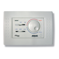
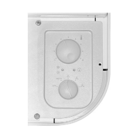
Panel is pre-set to this mode, switching off when temp is reached.
Fan remains on even when target temp is met. Requires jumper removal.
Automatically switches between heating/cooling based on room temp.
Use the OFF-ON cursor to switch the fan coil on or off.
Use the knob to select desired temperature; range 10°C to 30°C.
Manually choose from low, medium, or high ventilation speeds.
Important safety precautions before starting electrical work and installation.
Description of panel fitting, plates, and ventilation mode selection.
Advice on installation placement, height, and wire connection guidelines.
Wiring diagram for a 2-tube fan coil system with a valve.
Wiring diagram for a 4-tube fan coil system with two valves.
Wiring diagram for a 2-tube fan coil system with a valve and electric heater.
| Category | Control Panel |
|---|---|
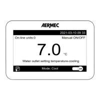
| Communication | RS485 Modbus RTU |
| Operating Temperature | 0°C to +50°C |
| Display | LCD |
| Buttons | 6 |