Do you have a question about the AERMEC PTI and is the answer not in the manual?
Describes the fancoil panel's location and how to secure it.
Explains how the thermostat regulates fancoil operation for set temperature.
Details automatic switching between heating and cooling based on water temperature.
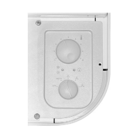
Lists and describes the main components of the control panel.
Explains the functions of the speed selector switch (OFF, AUTO, manual speeds).
Describes how to set the desired temperature using the selector.
Details how the unit automatically switches between heating and cooling.
Explains the meaning of the LED indicator lamp colors.
Describes different fancoil unit types and configurations PTI panels support.
Explains manual/automatic fan speed control and delay settings.
Covers controls, thresholds, and status indicators for water temperature.
Describes the two valve control modes (Optimised, Normal).
Explains operation in emergency mode due to ambient probe fault.
Warns that installation must be done by qualified personnel only.
Lists the parts included in the PTI kit for installation.
Specifies environmental conditions for panel installation.
Outlines the general steps for installing the control panel.
Details the standard installation procedure for the right-hand side.
Details the procedure for installing the panel on the left-hand side.
Emphasizes disconnecting power before any electrical intervention.
States that each control panel is designed for a single fancoil.
Instructs to follow provided wiring diagrams for all connections.
Alerts that all PTI panel components operate at 230V AC.
Explains panels are ready for standard use but adjustable via dipswitches.
Introduces the dipswitch settings and their purpose.
Emphasizes that Dip 1 and 2 must have the same settings for correct operation.
Configures shut-off valve and water probe position settings.
Configures the valve control mode (Optimised/Normal).
Adjusts probe correction for heating to compensate metal structure.
Enables heating/cooling modes based on water temperature settings.
Explains the Autotest function's purpose: checking fan, valves, and heaters.
Details the step-by-step process to activate and run the Autotest.
Describes valve/fan speed activation and LED indications during Autotest.
States that the Autotest function automatically stops after one minute.
Provides a key to understand the symbols and abbreviations used in wiring diagrams.
Defines the abbreviation MV for Fan Motor.
Defines the abbreviation PE for Earth Connection.
Defines the abbreviation SA for Room Sensor.
Defines the abbreviation SW for Water Temperature Sensor.
Defines the abbreviation VCF for Solenoid Valve.
Lists wire color abbreviations and their corresponding colors.
| Brand | AERMEC |
|---|---|
| Model | PTI |
| Category | Control Panel |
| Language | English |