Do you have a question about the AERMEC PCO5 and is the answer not in the manual?
Explains the pGDx panel's menu structure and the meaning of its icons.
Details the home menu, general unit status, and operating states.
Monitors chiller operating modes, setpoints, and multifunction inputs.
Manages double setpoints and setpoint compensation via multifunction input.
Selects compressor units for dialogue and manages control cards.
Configures time, date, timers, and daily operating zones.
Accesses system settings and allows language selection.
Monitors digital I/O, transducer readings, and water temperatures.
Displays compressor, gas, software, and valve status information.
Monitors specific temperature and gas sensor readings.
Consults active alarms, views history, and performs alarm resets.
Classifies alarms by type (signal, circuit, serious, gas) and lists sources.
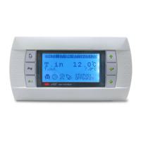
Covers the initial start-up procedure and the function of PGD1 control panel keys.
Details the PGD1 menu structure and user operating procedures.
Displays general unit status and operating states of compressors/pumps.
Shows the last 25 alarms with stored parameters.
Identifies machine status and changes general enabling.
Graphs water temperatures and cooling capacity over time.
Accesses installer menu, configures probes/transducers, and sets pressure limits.
Configures supervisor functionality, setpoints, and temperature controls.
Configures gas type, BMS, input, and output parameters.
Configures digital contacts, power requests, and language settings.
| Frequency | 50/60 Hz |
|---|---|
| Humidity | 10% to 90% RH (non-condensing) |
| Protection Degree | IP20 |
| Weight | 0.5 kg |
| Operating Temperature | -10°C to 60°C |
| Storage Temperature | -20 ÷ 70 °C |
| Power Consumption | 5 VA |