EasyManua.ls Logo

AERMEC PXA I User Manual

AERMEC PXA I
7 pages
To Next Page IconTo Next Page
Page #1 background imageLoading...
Page #1 background image
ISO 9001 - Cert. n° 0128/4
APXAIUJ
0609
50738.50_01
PXA I
PANNELLO COMANDI ELETTRONICO PER
VENTILCONVETTORI
INSTALLAZIONE A BORDO DEL VENTILCONVETTORE
ELECTRONIC CONTROL PANEL FOR FAN COILS
INSTALLATION ON THE FAN COIL
PANNEAU DE COMMANDE ELECTRONIQUE POUR
VENTILO-CONVECTEURS
INSTALLATION EMBARQUÉE SUR LE VENTILO-CONVECTEUR
ELEKTRONISCHE BEDIENTAFEL FÜR
GEBLÄSEKONVEKTOREN
INSTALLATION AM GEBLÄSEKONVEKTOR
TABLERO DE MANDOS ELECTRÓNICO PARA FAN COILS
INASTALACIÓN A BORDO DEL FAN COIL
MANUALE D’USO E INSTALLAZIONE
USE AND INSTALLATION MANUAL
MANUEL D'UTILISATION ET D'INSTALLATION
BEDIENUNGS- UND INSTALLATIONSANLEITUNG
MANUAL DE USO E INSTALACIÓN
Question and Answer IconNeed help?

Do you have a question about the AERMEC PXA I and is the answer not in the manual?

AERMEC PXA I Specifications

General IconGeneral
BrandAERMEC
ModelPXA I
CategoryControl Panel
LanguageEnglish

Summary

PXA I Control Panel Overview and Operation

Control Panel Components

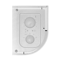
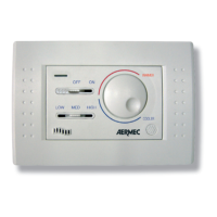
Identifies main controls (selectors) and indicators (LEDs) on the PXA I unit.

Fan Coil Operation Modes

Explains Frost Protection, All Off, and Ventilation modes for fan coils.

Automatic Air Side Mode Switching

Describes the automatic changeover between heating and cooling based on system parameters.

Using the PXA I Control Panel Features

Adjusting Fan Speed and Temperature

Details how to set desired room temperature and fan speed using selectors.

Interpreting Indicator Lights

Explains the meaning of the different colored indicator lights on the panel.

Dip-Switch Configuration for System Settings

Sw1 and Sw2 Dip-Switch Functions

Outlines the purpose of each dip-switch for plant type, probe position, and management settings.

Installation, Fixing, and Testing Procedures

Installation Safety Warnings

Critical safety precautions to be followed during installation.

Mounting and Wiring the Control Panel

Step-by-step guide for physically installing the panel and making electrical connections.

Performing the Installation Autotest

Instructions for running the autotest to verify the functionality of the unit.

Wiring Diagrams and Cable Requirements

Wiring Diagram Symbol Legend

Explains the meaning of symbols used in the electrical wiring diagrams.

Specifications for Connection Cables

Lists the required specifications and types for connection cables.

Related product manuals