Do you have a question about the AERMEC PGD1 and is the answer not in the manual?
Explains the organization of the unit's functions and information into menus and windows for easy navigation and operation.
Details the icons used in the pGDx panel menus, explaining the function of each icon for machine status and navigation.
Describes icons used in the Home menu to identify machine components like compressors, valves, and pumps, and their status.
Allows identification of the machine status and general enabling, displaying operating mode and machine status.
Displays and allows modification of current cooling and heating setpoints, including limits and external demand.
Monitors multifunction inputs, showing limits, capacity, and setpoint compensation values from external sources.
Displays the last 25 alarms with associated parameters, allowing download of the alarm log to USB.
Allows viewing and modification of the system's time, date, and day of the week parameters.
Enables and configures the weekly time band timer to manage chiller activity based on time zones.
Illustrates the programmed operating zones based on the weekly time band timer, showing ON/OFF periods.
Displays the status of all digital inputs and outputs, indicating their operational state.
Shows readings from various transducers and probes, including pressure, temperature, and multifunction inputs.
Monitors the temperature of the condenser water at both the inlet and outlet points.
Specifically monitors the condenser water outlet temperature.
Tracks the cumulative operating hours for the evaporator pump, condenser pump, and compressors.
Displays software versions and readings from flammable gas leak detectors.
Shows compressor status details including suction, discharge, oil temperature, speed, and gas type.
Provides a summary of compressor status like state (stopped, starting, running) and envelope zone status.
Monitors the status and evolution of electronic valves, including pressure, temperature, and position.
Displays a live diagram of water inlet and outlet temperatures over time.
Shows a live diagram of the cooling capacity output by each compressor.
Allows selection of the system language for all descriptions and messages displayed on the unit.
Contains parameters for machine configuration and functions, accessible with a password.
Lists alarms that provide only a signal on the display and alarm relay.
Details alarms that deactivate only the relative circuit, with display and alarm relay signals.
Describes alarms that deactivate all system circuits, triggering display and alarm relay signals.
Alarms related to the management of flammable gas, requiring specific handling.
Procedure for resetting active alarms, emphasizing caution and when to seek assistance.
Details the process for resetting gas alarms, which requires a password for safety.
A comprehensive list of all alarm codes, descriptions, sources, and types for system troubleshooting.
Describes the initial operations performed by the control card after powering up, including language selection.
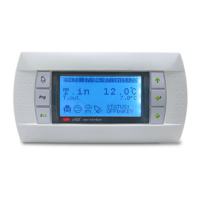
Explains the function of each key on the PGD1 control panel for navigation and parameter modification.
Illustrates the menu hierarchy and relationships between menus and navigation keys on the control panel.
Guides the user on basic operations like moving between menus and selecting/modifying parameters.
Displays the status of all digital inputs and outputs, summarizing machine status and circuit operation.
Monitors readings from high and low pressure transducers, providing current values in bar.
Displays readings from TIA, TUAC, and TGP probes, related to water inlet and discharge gas temperatures.
Monitors transformer inlet temperature and evaporator water outlet temperature.
Displays evaporator inlet gas temperature and multifunction input values.
Monitors condenser water temperature at both inlet and outlet.
Specifically monitors the condenser water outlet temperature.
Displays the voltage value at the analogue output YO.
Shows the software version and release date of the AerMEC unit.
Provides status details for compressors, including speed, envelope status, and gas type.
Summarizes compressor status like state (stopped, running) and envelope warnings.
Details inverter input status such as suction, discharge, oil temperature, and timing.
Monitors the gas level detected by sensor 1, indicating flammable gas concentration.
Monitors the gas level detected by sensor 2, indicating flammable gas concentration.
Displays the pressure, temperature, and position status of electronic valves 1 and 2.
Allows selection of the operational mode and displays the current setpoint for adjustment.
Displays and allows modification of cooling and heating setpoints.
Allows configuration of double cooling and heating setpoints, if enabled.
Shows the currently used setpoint, limit, and external demand values.
Monitors multifunction input for setpoint setting, displaying input values and setpoints.
Monitors multifunction input for cooling capacity limitation, showing input values and limits.
Monitors multifunction input for cooling capacity request, displaying input values and requested capacity.
Monitors multifunction input for setpoint compensation, displaying input values and compensation amounts.
Allows viewing and modification of the system's time, date, and day of the week.
Enables and configures the weekly time band timer for managing chiller activity.
Allows modification of the day of the week and times for Time Zone 1.
Allows modification of the times for Time Zone 2.
Visualizes the programmed operating zones for each day of the week.
Prompts for the password to access the installer menu for machine configuration.
Enables or disables probes and transducers (B1-B6) for system monitoring.
Enables or disables probes and transducers (B7-B10) for system monitoring.
Configures the full-scale limits for the high-pressure transducer's 4-20mA signal.
Configures the full-scale limits for the low-pressure transducer's 4-20mA signal.
Enables digital inputs for remote on/off and cooling/heating commands.
Enables supervisor commands for on/off and cool/heat functions.
Enables supervisor demand and demand limit functionalities for system control.
Enables the use of double setpoints, typically controlled via a digital input.
Enables heater alarms for the evaporator pump circuit breaker and pump off with compressor.
Configures temperature selection (inlet/outlet) and probe position for adjustment.
Sets the type of adjustment (P, I, PI) and integration time for control.
Sets the temperature band for thermostat adjustment.
Specifies the type of refrigerant gas used by the system.
Displays the number of electronic valves (EEV) present in the system.
Manages glycol water settings and monitors the freezing temperature.
Configures Building Management System (BMS) parameters like address, baudrate, and protocol.
Configures BMS2 parameters, including address, baudrate, and protocol for a second BMS.
Configures multifunction inputs, defining function, type (NTC, 0-10V, 4-20mA), and parameters.
Configures NTC probe temperature settings, including minimum and maximum values.
Configures 0-10 Volt multifunction input settings, defining minimum and maximum input voltage.
Configures 4-20mA multifunction input settings, defining minimum and maximum input current.
Configures cooling setpoint settings for external demand, including low and high values.
Configures heating setpoint settings for external demand, including low and high values.
Configures multifunction input for cooling capacity limit, setting low and high power limits.
Configures multifunction input for external power requests, setting demand low and high values.
Configures multifunction input for cooling setpoint compensation, defining low and high compensation values.
Configures multifunction input for heating setpoint compensation, defining low and high compensation values.
Enables digital contacts for external power requests.
Sets the digital contact power steps (Step 1, 2, 3) for external requests.
Enables Pull Down control and sets temperature rate and delay parameters.
Allows selection of the system language from a list of available languages.
Allows setting a new password for resetting gas alarms.
Allows setting a new password for accessing the installer menu.
| Brand | AERMEC |
|---|---|
| Model | PGD1 |
| Category | Control Panel |
| Language | English |