EasyManua.ls Logo

AERMEC FMT 20 AW User Manual

AERMEC FMT 20 AW
32 pages
Go to English
To Next Page IconTo Next Page
Page #1 background imageLoading...
Page #1 background image
ISO 9001 - Cert. n° 0128/4
PANNELLO COMANDI ELETTRONICO PER
VENTILCONVETTORI
INSTALLAZIONE A PARETE
ELECTRONIC CONTROL PANEL FOR FAN COILS
WALL-MOUNTED INSTALLATION
PANNEAU DE COMMANDE ELECTRONIQUE POUR
VENTILO-CONVECTEURS
INSTALLATION MURALE
ELEKTRONISCHE BEDIENTAFEL FÜR
GEBLÄSEKONVEKTOREN
ZUR WANDMONTAGE
TABLERO DE MANDOS ELECTRÓNICO PARA FAN COILS
INSTALACIÓN DE PARED
MANUALE D’USO E INSTALLAZIONE
USE AND INSTALLATION MANUAL
MANUEL D'UTILISATION ET D'INSTALLATION
BEDIENUNGS- UND INSTALLATIONSANLEITUNG
MANUAL DE USO E INSTALACIÓN
FMT 20 AW
AFMT20AWUJ
0809
63523.21_00
Question and Answer IconNeed help?

Do you have a question about the AERMEC FMT 20 AW and is the answer not in the manual?

AERMEC FMT 20 AW Specifications

General IconGeneral
Frequency50/60 Hz
Power Consumption5 VA
Operating Temperature0°C to +50°C
Storage Temperature-20°C to +60°C
DisplayLCD
CommunicationModbus RTU

Summary

Technical Specifications

Functions

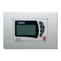
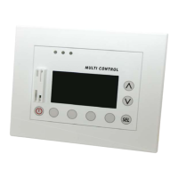
Details core functionalities like mode selection, temperature control, and ventilation.

Water Temperature Control (SWA)

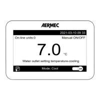
Controls water temp for heating/cooling using SWA accessory.

System Alarms

Indicates water temp or air temp issues with Fail icon.

Automatic Changeover

Automatically establishes Heating or Cooling based on temperature.

Switching On and Off

Selecting Working Mode

Explains how to choose between Heat, Cool, Automatic, and Fan modes.

Installation Instructions

Power Disconnection Warning

Crucial safety warning to disconnect power before installation.

Qualified Personnel Requirement

Installation must be performed by qualified and experienced technicians.

SWA Probe Installation

Guidance for installing the SWA accessory probes.

Water Temperature Sensing

Using SWA probe for water temperature control in 2-pipe systems.

Air Temperature Sensing

Using SWA probe for room air temperature detection.

Wiring Diagrams

2-Tube Fan Coil Wiring

Diagram for a 2-tube fan coil system with valves.

4-Tube Fan Coil Wiring

Diagram for a 4-tube fan coil system with 2 valves.

2-Tube Fan Coil with Heater Wiring

Diagram for a 2-tube fan coil with valve and electric heater.

Related product manuals