Do you have a question about the AERMEC MULTI CONTROL and is the answer not in the manual?
Guidance on keeping manuals dry to prevent deterioration and for future reference.
Guidance on keeping manuals dry to prevent deterioration and for future reference.
Details on systems managed without additional VMF CRP modules, focusing on cooling/heating production.
Details on systems managed with additional VMF CRP modules, including DHW and remote control.
Details on connecting VMF CRP 1 module for managing 3-way diverter valves and system probes.
Details on connecting VMF CRP 2 module for supplementary electric resistance management in DHW.
Details on connecting VMF CRP 3 module for remote control management of system functions.
Information on serial connection setup for integrating with a BMS supervision system.
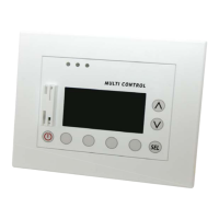
Overview of the panel's control keys and their corresponding functions during operation.
Explains the main menu structure and how to navigate through different sections.
User and Installer password values required to access protected system parameters.
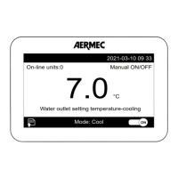
Description of icons and information displayed on the main MULTI CONTROL screen.
Details on parameters displayed in the MONITOR mode for system chillers.
Instructions on how to switch the entire system on or off from the main screen.
Instructions on how to enter menu selection mode and browse through the system menus.
Monitoring the operational status of connected chillers, including on/off, standby, and fault indicators.
Viewing specific operating parameters of selected chillers, such as temperatures and pressures.
Table detailing how operating parameters correspond with different types of chiller units.
Configuring up to two daily time periods for chiller operation based on the day of the week.
Configuring daily time periods for DHW production, allowing scheduled operation of the heat pump.
Setting the time and days for the anti-legionella cycle to ensure water safety.
Monitoring the status of heat pump and supplementary heat sources for domestic hot water production.
Procedure for setting the current time on the MULTI CONTROL panel for all system timers.
Procedure for setting the current date on the MULTI CONTROL panel, including the day of the week.
Configuring the system season (Winter or Summer) to manage chiller operation logic.
Setting the interface language and adjusting the visual contrast of the LCD display.
Setting the idle time before the screen saver automatically activates and returns to the main screen.
Viewing the log of the last ten triggered alarms, including unit, index, label, time, and date.
Detailed explanations for various alarm labels, their origin, and their corresponding descriptions.
Configuring the heating operating set-point for units installed in the system.
Configuring the cooling operating set-point for units installed in the system.
Setting compensation functions based on external air temperature for heating or cooling modes.
Defining the type of unit (Cooling Only, Heating Only, Heat Pump) for proper system management.
Configuring the number of units designated for domestic hot water production.
Specifies Modbus addresses for DHW units in systems without a reserve chiller.
Specifies Modbus addresses for DHW units in systems including a reserve chiller.
Enabling or disabling simultaneous activation of unit compressor, resistance, and tank resistance for DHW.
Configuring the delay time before the RAS (DHW tank resistance) activates if DHW demand is not met.
Setting the rotation time for the 3-way diverter valve to prevent flow switch alarms during DHW production.
Defining the ON/OFF band for DHW production to establish activation/deactivation temperatures.
Adjusting the DHW production settings of secondary units by a specified hysteresis delta value.
Setting the direction of water flow (system or DHW circuit) during defrosting cycles in DHW production.
Configuring the type of remote control applied to the MULTI CONTROL accessory (VMF CRP 3 or BMS).
Table of Modbus addresses for creating a BMS system, detailing access, value ranges, and descriptions.
Configuring the communication speed (baud rate) for the serial port used for BMS systems.
Setting the serial port address for BMS systems, with possible values ranging from 0 to 247.
Configuring whether VMF CRP expansion modules (1, 2, 3) are present in the system.
Checking the status of the serial network, indicating communication status of system elements and modules.
Configuring the total number of units managed by the MULTI CONTROL accessory.
Activating or deactivating the reserve chiller option, to be used in case of main chiller failure.
Defining the logic for rotating unit switching on/off (Fixed Sequence or Balanced Sequence).
Setting the management logic for units (FREE, LOAD, or DELTA T control).
Configuring the delay time for switching units on and off, ensuring smooth system operation.
Setting power percentage thresholds for requesting secondary units to switch on or off.
Configuring the activation temperature for units when DELTA T control logic is applied.
Configuring the deactivation temperature for units when DELTA T control logic is applied.
| Brand | AERMEC |
|---|---|
| Model | MULTI CONTROL |
| Category | Control Panel |
| Language | English |