Do you have a question about the AERMEC VMF-E2 and is the answer not in the manual?
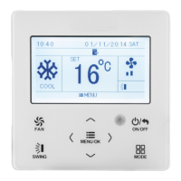
Describes the electronic control panel for fan coil units within the VMF system.
Covers warnings on unit usage, static electricity, temperature, malfunctions, and cable handling.
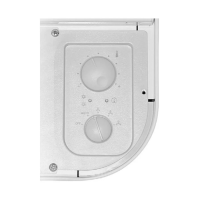
Description of the physical layout and controls on FCX and FCZ models.
Explains the temperature selector and operation mode indicator light.
Details on ventilation speed selection and indicator lights.
Illustrates standard and optional temperature settings for heating, cooling, and frost protection.
Instructions for initiating and ceasing fan coil operation.
How to select and adjust fan speed settings including AUTO and manual modes.
Guidance on setting desired temperatures and managing automatic season changes.
Meaning of the YELLOW LED D for ventilation status and faults.
Explanation of LED C colours indicating heating, cooling, and frost protection modes.
Interpreting special LED combinations for addressing, serial numbers, and communication issues.
Essential safety warnings and general guidelines for installing the device.
Instructions for making electrical connections and wiring diagrams.
| Protection Degree | IP30 |
|---|---|
| Power Consumption | 5 VA |
| Operating Temperature | 0°C to 40°C |
| Storage Temperature | -20 °C to 70 °C |
| Relative Humidity | 5% to 95% non-condensing |
| Communication | Modbus RTU |
| Display | LCD |
| Buttons | 6 |