Do you have a question about the AERMEC VMF-E2D and is the answer not in the manual?
Guidelines to prevent damage from electrostatic discharge and accumulation.
Only use 230V single-phase voltage for the fan coil to prevent damage.
Recommendations for room temperature settings to ensure comfort and efficiency.
Procedure for handling malfunctions: power cycle and contact service.
Caution against pulling, treading on, or crushing the electric power cable.
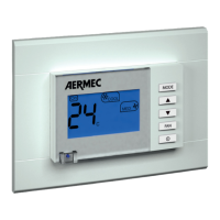
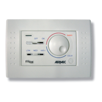
Control for adjusting the desired temperature setting.
Indicates the active operating mode (Red, Blue, Fuchsia).
Selector for fan speed (OFF, AUTO, V1, V2, V3).
Indicates when the fan is requested (Yellow light).
Instructions on how to start and stop the fan coil unit using the control knob.
Explanation of automatic and manual fan speed selection modes.
How to adjust the room temperature using the selector knob.
How to change operating mode (heating/cooling) by adjusting louvres.
Meaning of the Yellow LED D status (ON, OFF, flashing).
Meaning of LED C colors (Red, Blue, Fuchsia) for operating modes.
Interpreting special LED combinations for specific operating conditions.
An illustration showing an example of a temperature set point configuration.
General guidelines and warnings before starting installation.
Instructions for installing the VMF-E2D accessory unit.
Specific steps for installing with a water valve, including sensor replacement.
Procedure for units with right-side connections, involving moving thermostat housing.
Specific installation notes for OMNIA ULI models regarding component placement.
Explanation of symbols and abbreviations used in the wiring diagrams.
Schematic for the electrical connections of a single DUALJET unit.
Schematic for electrical connections in a master-slave DUALJET system.
| Frequency | 50/60 Hz |
|---|---|
| Protection Degree | IP20 |
| Communication Protocol | Modbus RTU |
| Operating Temperature Range | -10°C to +50°C |
| Storage Temperature Range | -20 ÷ 70 °C |