Do you have a question about the AERMEC PXL 2 E and is the answer not in the manual?
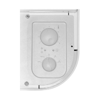
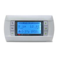
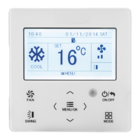
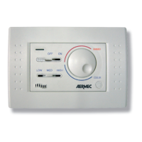
Identifies main selector switches, keys, and indicator LEDs on the control panel.
Explains Comfort, Economy, Frost Protection, and All Off operational modes.
Details ventilation modes and automatic water-side changeover functions.
Describes the operation of speed and temperature selector switches.
Explains the function of the Heating/Cooling and Economy keys.
Explains the status indicated by the yellow, green, and red LEDs.
Introduces DIP switch settings for operating modes and external contacts.
Details temperature settings and dead zones based on DIP switch configurations.
Provides explanations for specific SW1 and SW2 dip switch functions.
Essential safety warnings and general installation procedures.
Guides for panel mounting, wiring, and cable specifications.
Visual diagram and explanation of SW1 and SW2 dip switch functionalities.
Step-by-step guide for activating, running, and exiting the autotest mode.
Explains the legend for wiring diagrams and connections to the terminal board.
Details electrical data, working conditions, and CE conformity standards.
| Power Consumption | 5 VA max |
|---|---|
| Number of Relays | 2 |
| Operating Temperature | 0°C to +50°C |
| Display | LCD |
| Communication | Modbus RTU |
| Relay Contact Rating | 5 A, 250 V AC |
| Relative Humidity | 10% to 90% non-condensing |