EX = Contatto esterno • External contact
Contact extérieur • Externer Kontakt
IG = Interruttore magnetotermico • Main switch
Interrupteur général • Hauptschalter
L = Morsettiera • Terminal board
Alimentation • Speisung
M = Morsettiera • Terminal board
Boitier • Klemmleiste
N = Morsettiera • Terminal board
Alimentation • Speisung
PE = Collegamento a terra • Earth wire
Mise à terre • Schutzerde
SC = Scheda di controllo • Electronic card
Platine de contrôle • Steuerschaltkreis
SW3 = Sonda acqua batteria (accessorio)• Water sensor (accessory)
Sonde eau (Accessoire) • Fühler Wassertemperatur (Zubehör)
VCF = Valvola solenoide • Solenoid valve
Vanne à trois voies • Dreiwegeventil
Moteur ventilateur • Ventilatormotor:
V1 = Velocità minima • Minimum fan speed
Vitesse minimale • Mindestgeschwindigkeit
V2 = Velocità media • Medium fan speed
Vitesse moyenne • Mittlere Geschwindigkeit
V3 = Velocità massima • Maximum fan speed
Vitesse maximale • Höchstgeschwindigkeit
15
LEGENDA • READING KEY • LEGENDE • LEGENDE
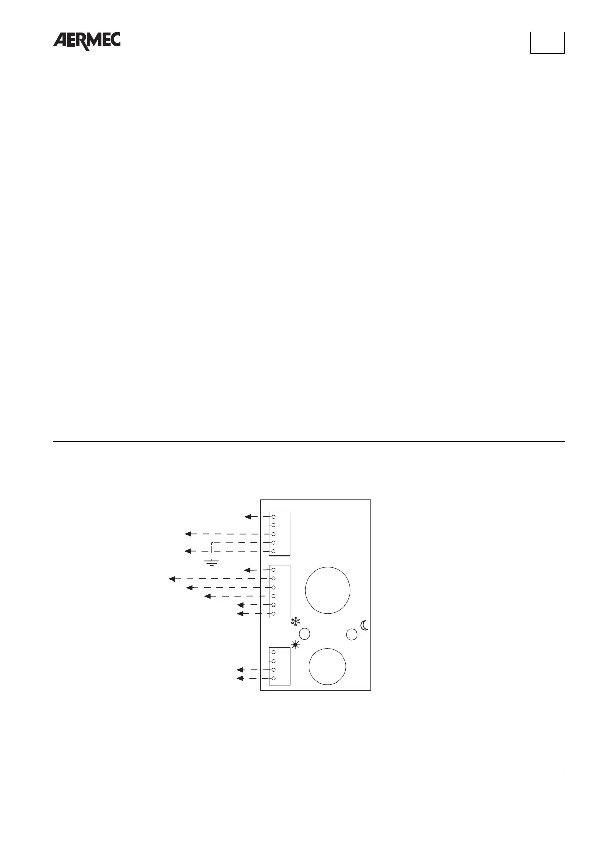
SCHEMI ELETTRICI • WIRING DIAGRAMS • SCHEMAS ELECTRIQUES • SCHALTPLANE
Gli schemi elettrici sono soggetti ad aggiornamento; è opportuno fare riferimento allo schema elettrico allegato all' apparecchio.
Wiring diagrams may change for updating. It is therefore necessary to refer always to the wiring diagram inside the units.
Les schémas électriques peuvent être modifies en conséquence des mises à jour. Il faut toujours se référer aux schémas électriques dans les appareils.
Die Schaltschemas können geändert werden; es empfiehlt sich immer auf das mit dem Zubehör verpackte El. Schaltschema zu beziehen.
Fig. 15
Lo schema elettrico indica
solo le entrate alla morsettie-
ra del pannello comandi, per
i collegamenti con i ventil-
convettori consultare anche
gli schemi forniti a bordo
delle unità da abbinare.
The wiring diagram indicates
only the connections with the
terminal board of the control
panel. As for the connections
with the fan coils look them
up in the wiring diagrams
supplied with the units to be
combined with.
Le schéma électrique n'indi-
que que les liaisons au bor-
nier du panneau des com-
mandes.
Pour les liaisons aux ventilo-
convecteurs, il faut consulter
même les schémas fournis sur
les unités à coupler.
In dem Schaltplan sind nur
die Elt. Anschlüsse an der
Klemmleiste der
Fernbedienung angegeben;
fuer die Elt.Verdrahtung des
Geblaesekonvektors ist der
im Geraet befindliche
Schaltplan zu verwenden.