EasyManua.ls Logo

AERMEC VXT User Manual

AERMEC VXT
48 pages
Go to English
To Next Page IconTo Next Page
Page #1 background imageLoading...
Page #1 background image
VXT
Pompa di calore condensata ad acqua
Electronic adjustment for water-cooled heat pumps
IVXTUI. 0907 - 4900563_00
MANUALE USO • USAGE MANUAL
IT GB
Pompa di calore condensata ad acqua
Question and Answer IconNeed help?

Do you have a question about the AERMEC VXT and is the answer not in the manual?

AERMEC VXT Specifications

General IconGeneral
ModelVXT
BrandAERMEC
Power Supply24 Vac/dc
DisplayLCD
CompatibilityAERMEC units
FunctionsControl and monitoring
CommunicationModbus RTU
Humidity5% to 95% (non-condensing)

Summary

Regulation features

User interface

PRDO (Accessory not supplied)

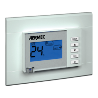
Describes the functionality and connection of the optional remote panel.

Notes regarding the guided commissioning procedure

Guided configuration procedure

Enter maintenance technician password (8430)

Specifies the procedure to access the technician level for configuration.

Selecting the types of heating terminals

Guides the user through choosing appropriate heating terminal types.

Selecting the types of cooling terminals

Guides the user through choosing appropriate cooling terminal types.

Selecting the type of circuit to the condenser (geothermy or well water)

Selecting the presence/absence of a system storage tank

Selecting the position of the regulation probe (storage tank or system)

Selecting presence/absence of an external air probe

Selecting presence/absence of the freecooling kit (accessory)

Selecting presence/absence of a source of integration

Selecting a source of the environment area control

Selecting the number of environment areas managed

Selecting mixer valve management

Selecting recirculation pump management

Selecting presence/absence of the solar heating kit (accessory)

Selecting the function assigned to the programmable digital contact

Enabling/Disabling On-Off from digital contact

Selecting the function assigned top the programmable output

Selecting the Plan network connection function

Select management via BMS

Selecting protocol for BMS

Selecting address for BMS

Selecting saving settings

Selecting activation/deactivation of the guided procedure

Menu structure and navigation

Icons key

Provides a reference guide to the meaning of various interface icons.

Using the keys, displays and parameters

Navigation and parameters modification operations

MENU selection page

Explains how to access the main menu selection screen.

DEFAULT page displayed

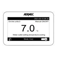
Describes the default screen shown upon unit activation.

Pass to another menu

Details the procedure for moving between different menus.

Pass from one page to another in the same menu

Explains navigation between pages within the same menu.

Selecting and modifying a parameter

Guides the user through selecting and changing parameter values.

MAIN MENU parameters

MAIN menu - PAGE O

Describes the initial page of the main menu, including date, time, and status.

MAIN menu - PAGE 7

MAIN menu - PAGE 9

MAIN menu - PAGE 10

MAIN menu - PAGE 11

MAIN menu - PAGE 12

MAIN menu - PAGE 13

MAIN menu - PAGE 24

MAIN menu - PAGE 26

SET-POINT MENU parameters

SET POINT menu - PAGE O

Describes the initial page of the Set-Point menu, including offset information.

SET POINT menu - PAGE 1

SET POINT menu - PAGE 2

SET POINT menu - PAGE 3

CLOCK MENU parameters

CLOCK menu - PAGE 1

Details time, date, and day settings for the Clock menu.

CLOCK menu - PAGE 2

Details weekly time periods for Comfort/Economy settings.

CLOCK menu - PAGE 3

CLOCK menu - PAGE 4

CLOCK menu - PAGE 5

CLOCK menu - PAGE 6

CLOCK menu - PAGE 7

CLOCK menu - PAGE 8

Alarms summary table

Related product manuals