34
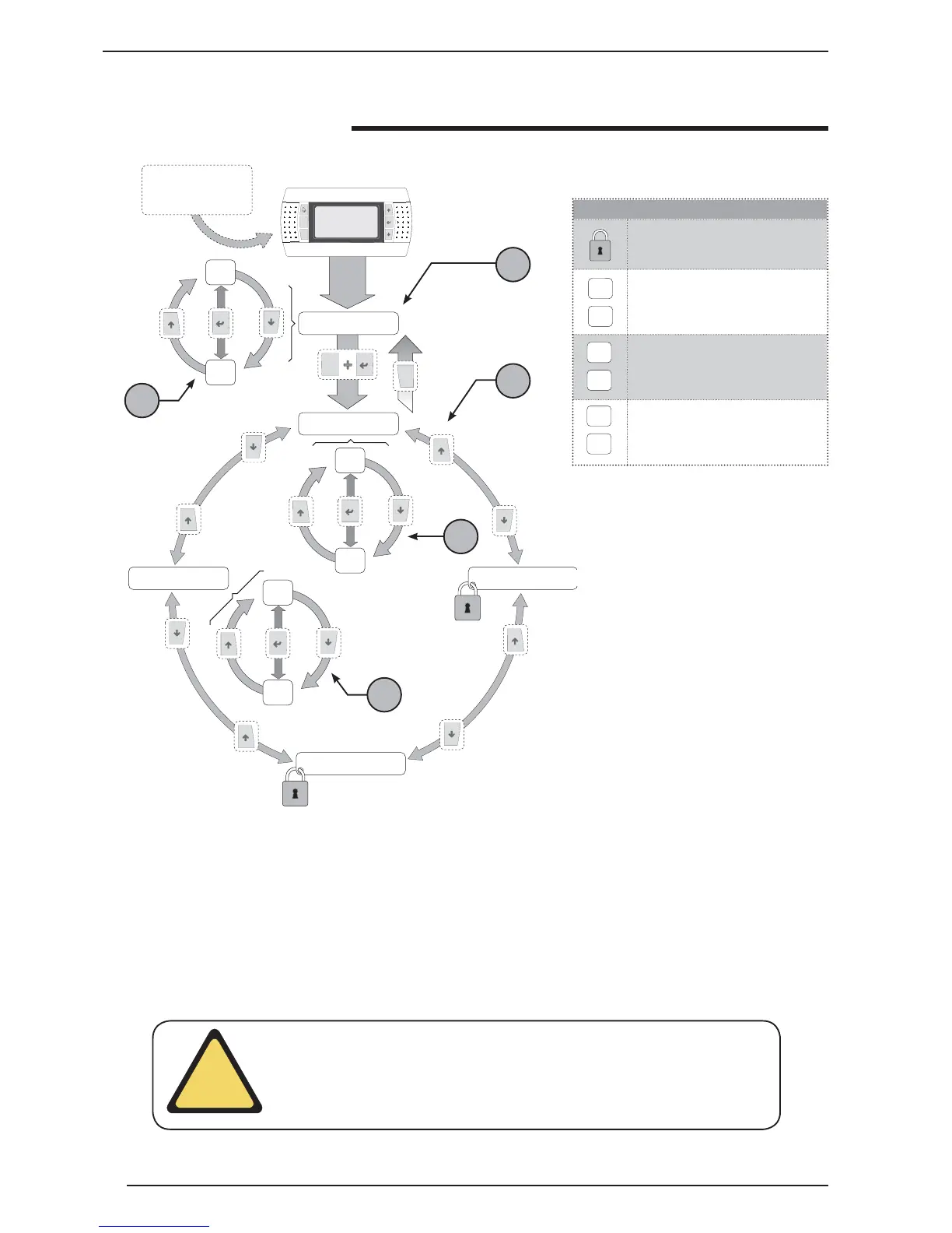
Menu structure and navigation
Icons key
Menu not available at user level
P0
P21
MAIN menu parameters index
S1
S15
SET-POINT menu parameters index
CK1
CK6
CLOCK menu parameters index
Prg
Esc
P0
P21
Menù principale
S1
S15
CK1
CK6
Menù set point
Menù manutentore
Menù costruttore
Menù orologio
Prg
Esc
Main menu
Set-point menu
Maintenance technician menu
Manufacturer’s menu
Clock menu
NOTE: the priority of levels 4 and 5 can be
reversed, on the basis of the navigation
system (clockwise/anti-clockwise).
The navigation in the various menus for
the management of the VXT unit is re-
presented by the layout shown above. In
this drawing the different operational le-
vels have been schematised, indicated
by a number:
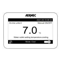
1 - Represents the default level, which
is accessed automatically once voltage
has been applied to the unit display;
2 - Represents the group of parameters
of the main menu and they are identi-
fi ed by a specifi c index indicated by
the letter P and a progressive number
which, unmistakably gives the page (for
this type of display the parameters have
not been numbered individually, but the
pages in which two or more linked para-
meters are displayed);
3 - Indicates the selection page betwe-
en the set-point, maintenance techni-
cian, manufacturer and clock menus;
4 - Represents the group of parameters
of the set-point menu (characterised by
the index S);
5 - Represents the group of parameters
of the clock menu (characterised by the
index CK);
It is possible to navigate in the various
operational menus using the keys de-
scribed in the upper screen, which
shows the navigation sequence from
one menu to another.
2
1
3
4
5
ATTENTION: remember that on commissioning, a sequence of screens will appear
dedicated to setting the system to which the unit is connected. These displays are
the exclusive competence of the technical staff authorised to install/set the fun-
ctioning parameters necessary for correct functioning of the unit.
!
Guided commissio-
ning procedure