35
Index Functions
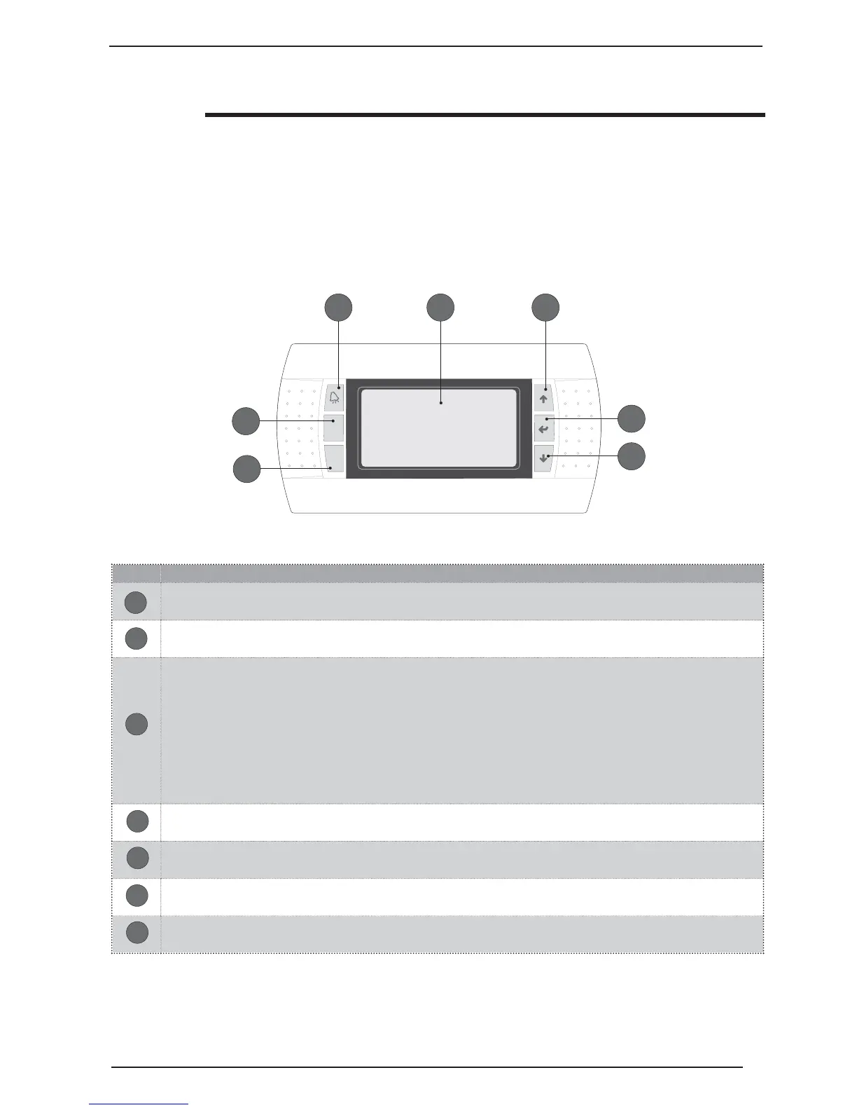
Graphical LCD, 130x37 pixels. This display allows to manage all unit functions. Any functioning anomalies are
also displayed.
Key for access to the ALARMS signals. Pressing once displays the alarm in progress, a second press eliminates the
display (alarm reset)
This key allows to access the menu selection screen, from among which one of the following can be selected:
SET-POINT
MAINTENANCE TECHNICIAN
MANUFACTURER
CLOCK
If this key flashes during normal functioning, it indicates the call to the compressor for functioning in progress (heating,
cooling, DHW etc...). Once flashing stops and the light becomes continuous, it means that the compressor is activated.
This key allows to go back to the upper level of the menu currently displayed
This key allows double regulation: scrolling upwards (in navigation mode) and increasing a parameter
(in modification mode)
This key allows to select a parameter, therefore allowing modification (same as ENTER key)
This key allows double regulation: scrolling downwards (in navigation mode) and decreasing a parameter
(in modification mode)
04/08/08 P0
FUNZIONAMENTOFUNZIONAMENTO
MODALITA'
UNITA'
15 :23
ON
ESTATE
ACCESA
Prg
Esc
B A
E
C
D
F
G
Using the keys, displays and parameters
The main user interface is represented
by a graphic display (120x32 pixel) with
six keys for navigation. The displays
are organised via a menu hierarchy,
which can be activated by pressing
the navigation keys (the procedure for
navigating in the menus, selecting the
set-points and their modifi cation is ex-
plained in the next page). The default for
displaying these menus is represented
by the main menu. During normal fun-
ctioning, the display shows the screens
relative to the main menu and the navi-
gation between the various parameters
takes place using the arrow keys po-
sitioned on the right side of the panel.
These keys are also used to modify the
parameters selected, according to the
procedure given in the following pages.
Moreover, the displays linked to every
parameter that the user can display and
the modifi cations he can make will be
shown.
A
B
C
D
E
F
G