14
GB
4598010_00
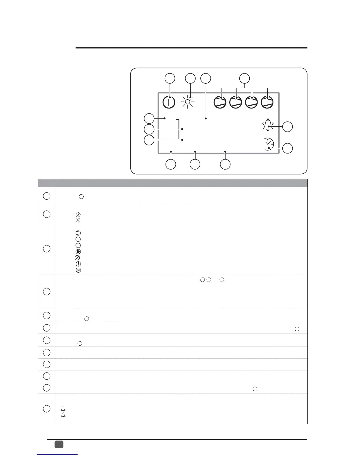
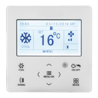
Main MULTI CONTROL display
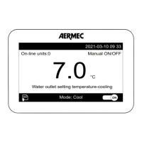
During normal operation of the system,
the MULTI CONTROL accessory
display shows the standard window.
This window contains information on
the system status and this information
will allow the user to have a clear
indication regarding functioning of the
chillers as well as supply any error and/
or malfunctioning messages.
Should the user enter a menu and not
press any key for a time longer than
that set in the screensaver function, the
system will automatically return to view
the main screen.
1234
WED 25/11/11 11 :23 :06
ON
OFF
U 1
TUA 37,7 C
O
TIA 31,3 C
O
SAE 10,1 C
O
B
C
N
M
LIH
D
A
• Main MULTI CONTROL screen:
Icon Function
A
Indicates the status of the system:
- if the icon ( ) is present, the system is on;
- if no icon is present, the system is off.
B
Indicates the selected season for the system:
- the icon ( ) indicates that the system is working in summer mode;
- the icon ( ) indicates that the system is working in winter mode.
C
Indicates the status of the connected chillers (the number below the symbol indicates which chiller the information refers to):
- the icon ( ) indicates that the chiller is on;
- the icon (
OFF
) indicates that the chiller is off;
- the icon (
SB
) indicates that the chiller is standby mode;
- the icon (
) indicates that the chiller pump is on;
- the icon( ) indicates that the chiller is not communicating with the modbus network of the system;
- the icon (
) indicates a failure in the chiller;
- the icon ( ) indicates that the chiller is defrosting.
D
Indicates which chiller the data currently displayed on the main window refers to (
E
,
F
and
G
): this parameter could indicate:
- U1: indicates that the data refers to chiller 1;
- U2: indicates that the data refers to chiller 2;
- U3: indicates that the data refers to chiller 3;
- U4: indicates that the data refers to chiller 4;
- MIX: indicates that the data refers to the SUW and SIW probes of VMF CRP expansion board (1).
E
Indicates the temperature of the water produced by the chiller currently viewed (the number of the chiller currently viewed as indicated by
the parameter
D
).
F
Indicates the inlet temperature of the chiller currently viewed (the number of the chiller currently viewed as indicated by the parameter
D
).
G
Indicates the outside air temperature detected by the chiller currently viewed (the number of the chiller currently viewed as indicated by the
parameter
D
).
H
Indicates the day of the week.
I
Indicates the system date (day/month/year).
L
Indicates the system time (hours/minutes/seconds).
M
Indicates whether the time period has been set in the system (for the chiller currently viewed in the parameter
D
).
N
Indicates an alarm status. this indication can represent different situations which can be recognised by the type of icon displayed:
- No icon means that no alarms are currently active;
- (
) an alarm not yet viewed in the alarm log is in progress;
- ( ) an alarm already viewed in the alarm log is in progress.
Should an alarm be triggered, these icons will appear until the cause of the alarm has been found.
E
F
G