15
8 DIAGRAM MENU
In this menu it is possible to consult the live updated diagrams of some sizes, which
are relevant for machine operation.
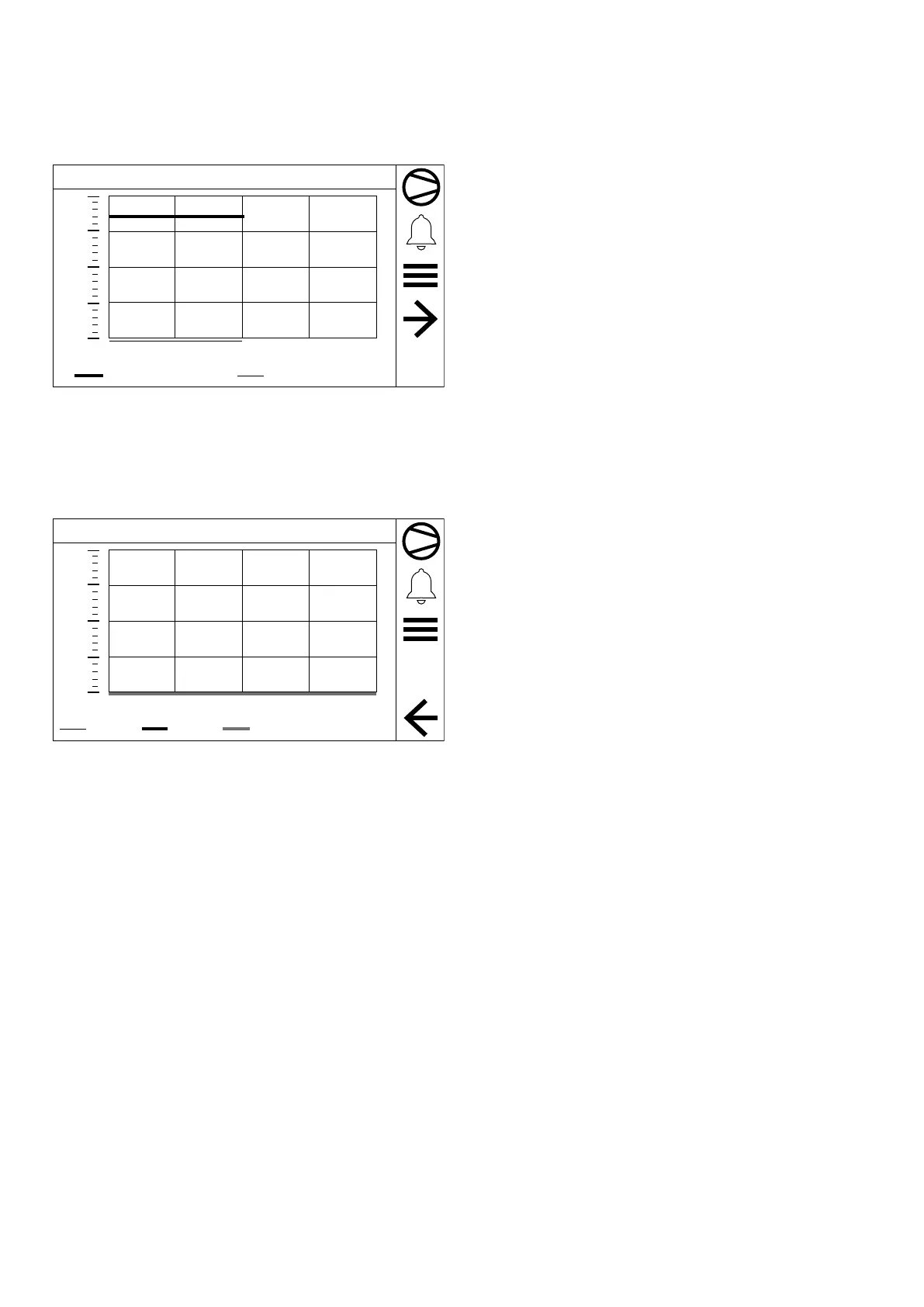
8.1 WATER INLET AND OUTLET TEMPERATURE MONITOR
1
10:29:20
10:24:13 10:26:43 10:29:13 10:31:43 10:34:13
0.0
3.4
6.8
10.1
13.5
[°C]
Inlet Temperature
Outlet Temperature
This mask is used to view the water inlet and outlet temperature.
NB: The diagram samples the values every 5 seconds and displays 30 minutes of
the log.
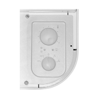
8.2 COOLING CAPACITY MONITOR
1
03/12/21 10:31:16
10:01:13 10:08:43 10:16:13 10:23:43 10:31:13
0.0
25.0
75.0
100.0
[%]
50.0
C1
C2
C3
Cooling capacity output by each compressor:
— Master
— Slave 1
— Slave 2
— Slave 3
NB: The diagram samples the values every 5 seconds and displays 30 minutes of
the log.