9
English
WARNING: before carrying out any
work, make sure the power supply is
unplugged.
WARNING: electrical wiring, installa-
tion of the fan coils and relevant acces-
sories should be performed by a techni-
cian who has the necessary technical
and professional expertise to install,
modify, extend and maintain systems
and who is able to check the systems
for the purposes of safety and correct
operation.
In the specific case of electrical connec-
tions, the following must be checked:
- Measurement of the electrical system
insulation strength.
- Continuity test of the protection wires.
Instructions essential for the proper
installation of the equipment are shown
here.
The completion of all the operations in
accordance with the specific require-
ments is however left to the experience
of the installation engineer.
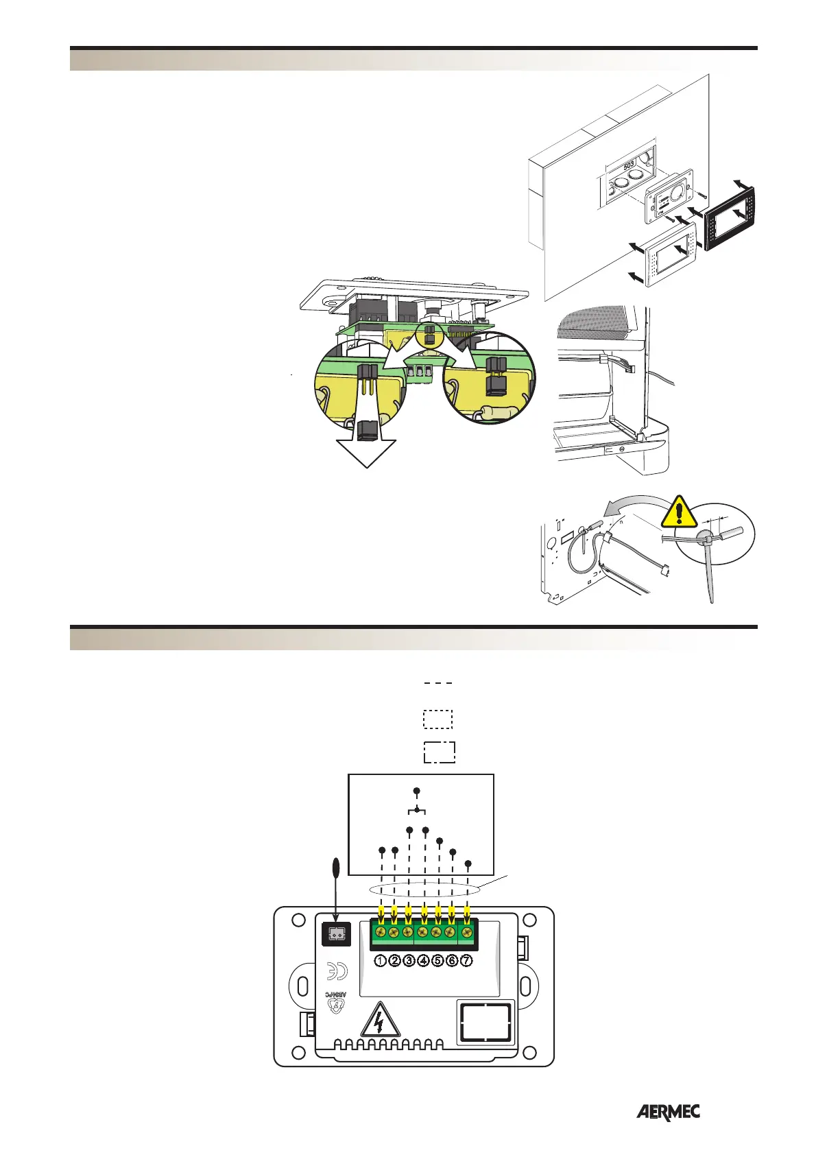
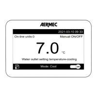
The command device is made up of an
electronic control panel, to be flush-
mounted in the wall in a standardised,
3-module rectangular box (type 503).
The control panel is fitted with two cove-
ring plates, a white one and a black one.
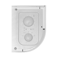
During the installation phase, it is pos-
sible to choose thermostat-controlled
ventilation or cont
inuous ventilation. The
thermostat is set for thermostat-controlled
ventilation. To set continuous ventilation,
it is necessary to remove the Jumper on
the electronic card (see picture). Avoid
installing the control panel in places
directly exposed to the rays of the sun,
draughts, heat sources and fan coil flow.
Install at a height of about 150cm from
the floor, on an internal, air-conditioned
wall.
Connect the wires to the control board
as indicated in the electrical layouts.
Use wires with a maximum length of 6
metres.
INSTALLATION
L
N
230V ~ 50Hz
EXT. SENSOR
L1
~
HIGH
MED
LOW
HEAT
COOL
L2 - N
C650 FS - 1C - 1H
VCF
FMT10
FAN COIL
VC
VF
Min.
Med.
Max.
MAX L=6m
AIR
L=6m
READING KEY
IG = Main switch
M = Terminal board
MS* = Microswitch
MV = Fan motor
PE = Earth connection
RX = Electric heater
VC = Three way valves (heat)
VCF = Three way valves (heat/cool)
VF = Three way valves (cool)
= On-site wiring
= Optional components
= Components not supplied
WIRING DIAGRAMS
106
71
AIRAIRAIR
20mm
FCX / FCS
AIR
All wiring diagrams are constantly updated. Please refer to the ones supplied with the unit.